
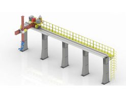
 Robot Linear track
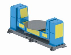 Robot welding Positioner
 Robot Torch cleaning station
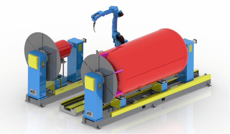 Welding Robot Workstations & Automation Solutions
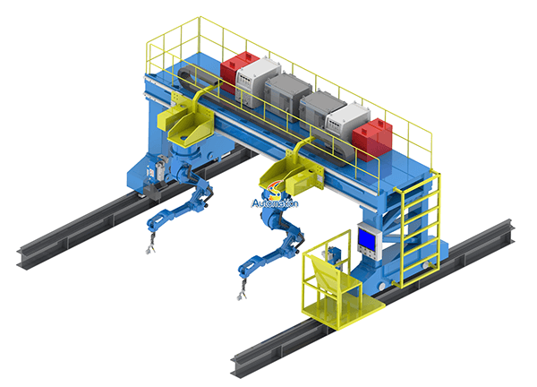 Robot Gantry System
The weld that never sits right
A heavy fabrication shop buys its first welding robot. The robot is good. The welding source is good. But the cell still struggles. The operator has to stop the program, unclamp the workpiece, crane it into a new position, re-clamp, and re-teach the seam. Some welds are done overhead because the part cannot be turned. Spatter falls into the joint. The welds look different from one side of the part to the other.
The problem is not the robot. It is the positioner — or the lack of one. A robot can only weld well when the joint is in front of the torch, in the downhand position, with the torch angle right. On a heavy workpiece, that only happens if something turns the part for the robot. That something is the welding positioner.
Choosing one sounds simple. Pick a load rating above your workpiece weight, and you are done. In practice, that is where most selection mistakes start. A positioner that is right for a 1-tonne pressure vessel can be wrong for a 1-tonne excavator boom. Same weight, completely different machine. This article explains why, and how to size a positioner the way an integrator does — starting from the workpiece, not the catalogue page.
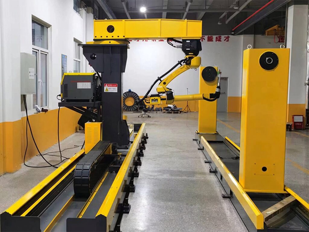
Start with the workpiece, not the catalogue
Every positioner selection we do starts with the same five questions. They are the same questions we ask any customer who sends us an inquiry:
- How heavy is the workpiece, including the fixture?
- How big is it — length, width, height, and where is its center of gravity?
- What shape is it — long and thin, flat and wide, round, or irregular?
- Which welds matter most, and what position do they need to be welded in?
- What robot will weld it, and how much reach does the robot have?
The fixture weight catches people out more than anything else. A 2-tonne workpiece on a 500 kg fixture is a 2.5-tonne load on the positioner. We have seen cells where the fixture alone used up a third of the positioner’s rating. Always size for workpiece plus fixture plus clamps, then add margin. If the workpiece will grow — a bigger variant next year, a heavier design revision — say so now. A positioner is a ten-year purchase. Buying for today’s part only is a false economy.
Shape matters as much as weight. A long, thin workpiece puts a very different load on a positioner than a compact one of the same weight. A long part creates a large tilting moment. A flat, wide part creates a large eccentric load when it is rotated off-center. The catalogue load rating assumes the load sits close to the rotation axis. Real workpieces rarely do.
Rated load is not the whole story: eccentric load and torque
This is the single most misunderstood number in positioner selection. A positioner rated for 3,000 kg does not hold any 3,000 kg workpiece in any position. It holds 3,000 kg when the center of gravity is close to the rotation axis. Move the center of gravity 300 mm off the axis, and the torque on the drive grows fast. Move it 500 mm, and the same positioner may stall, slip, or wear out its gearbox in a year.
Two numbers decide whether a positioner can hold your part:
Tilting torque is the torque needed to hold the workpiece when its center of gravity is offset from the tilt axis. It grows with weight times distance from the axis. A heavy part with a high center of gravity needs far more tilting torque than a compact part of the same weight.
Rotational torque is the torque needed to turn the workpiece around the rotation axis. It depends on the moment of inertia — how the mass is spread out around the axis — not just the total weight. A long beam is harder to rotate than a compact block of the same mass.
This is why we always ask for the workpiece drawing, or at least the center of gravity position, before quoting a positioner. Without it, any load recommendation is a guess. If you only have one number to send a supplier, send the center of gravity offset and the distance from the rotation axis. That tells us more than the weight alone.
A practical rule: if your workpiece’s center of gravity sits more than 200–300 mm from the rotation axis, tell the supplier. The standard rating probably does not apply, and the fix is usually a larger gearbox or a different positioner type — not a stronger motor.
One axis, two axes, or three?
The axis count decides which weld positions the robot can reach without re-clamping. It is the biggest cost step in positioner selection, so it is worth getting right.
Single-axis positioners rotate the workpiece around one axis — usually horizontal. They suit round or near-round parts: pipes, flanges, pressure vessel shells, wheels. The robot welds circumferential seams while the part turns. Simple, reliable, and the cheapest option. The limit is obvious: the part can only rotate, not tilt. If your welds need the part tilted to reach the downhand position, a single axis will not do it.
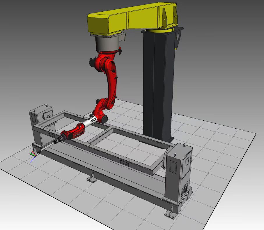
Two-axis positioners add a tilt axis. This is the workhorse of heavy-duty robotic welding. The tilt brings the joint into the flat position, and the rotation turns it under the torch. Most heavy fabrication — structural steel, construction machinery, agricultural equipment, pressure vessels — runs on two axes. Within two-axis machines there are several layouts, and the layout should match the workpiece shape (see the next section).
Three-axis positioners add a second rotation or a second tilt, usually for parts that need welding on several faces in one setup, or for long parts supported at two points that must tilt together. They cost more and need more programming. They pay for themselves when a part would otherwise need two or three re-clamping operations per cycle. If your cell spends more time loading and repositioning than welding, a third axis is worth pricing.
The mistake we see most often is buying one axis too few to save money, then paying for it every day in re-clamping time and inconsistent weld quality. The second most common is buying three axes for a part that only ever needs two. Count how many times the part must be re-clamped to weld every seam. If the answer is zero with two axes, two axes are enough.
Matching the positioner type to the workpiece
Two-axis positioners come in several shapes, and each one fits a different kind of workpiece. These are the types we build and see most often in heavy-duty cells:
Headstock–tailstock (head and tail beam). The workpiece is held between two ends and rotates around its long axis, with a tilt axis at one or both ends. This is the right choice for long parts: beams, booms, chassis frames, shafts, pressure vessels. The tailstock supports the far end, so the load is shared and the deflection stays small. For parts over about 2 metres long, a headstock–tailstock machine is usually the first option to look at. The key question is the distance between the two ends and how much the part sags in the middle.
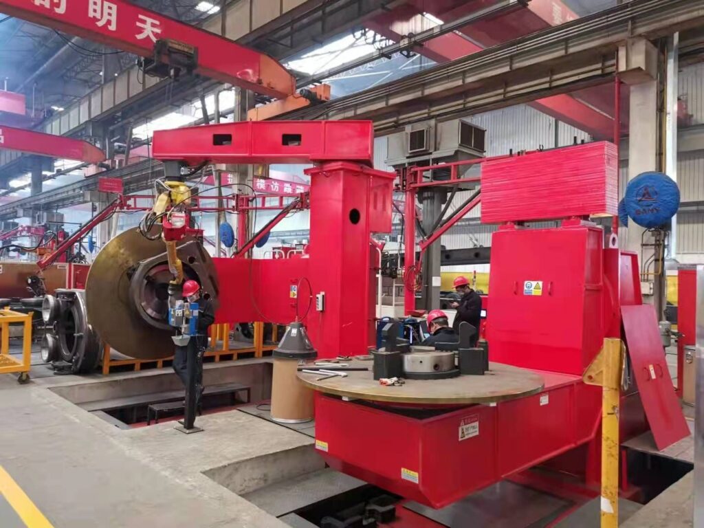
L-type. The workpiece mounts on a table that tilts around one axis and rotates around another, in an L-shaped arrangement. L-type positioners suit compact, heavy parts that need good access from several sides: brackets, housings, machine frames, valve bodies. They hold the part close to the tilt axis, which keeps the tilting torque down. If your part is heavy but compact, an L-type is often the most economical two-axis choice.
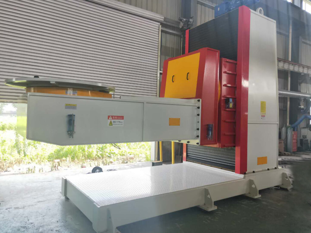
C-type. The workpiece sits inside a C-shaped frame and rotates within it. C-type machines suit round or ring-shaped parts and parts that need continuous rotation through a full 360 degrees without the fixture getting in the way. They give the robot good access all round the part.
U-type. Similar idea to the C-type, with the workpiece mounted across the open side of a U-frame. U-type positioners work well for medium-sized frames and box structures where the part needs to be tilted and rotated but the fixture must stay simple.
Platform (P-type). The workpiece bolts to a flat rotating table that can also tilt. Platform positioners suit large, flat, or irregular parts that cannot be clamped between two ends: base plates, large covers, welded assemblies with awkward shapes. The trade-off is that the center of gravity often sits further from the tilt axis, so the torque requirement is higher for the same weight. Always check the eccentric load on a platform machine.
S-type / skyhook. The workpiece hangs or mounts at an angle that keeps the rotation axis close to the weld. Skyhook-style positioners suit tall or awkward parts where a standard table would put the weld out of the robot’s reach.
There is no best type. There is only the type that fits your workpiece shape and your weld positions. When a supplier asks for the workpiece drawing, this is why. The shape decides the type, and the type decides the price.
Servo drive or variable-speed drive?
Not every positioner axis needs to move in coordination with the robot. This is a cost decision as much as a technical one.
Servo-controlled axes are driven by the robot controller as external axes. The robot and the positioner move together, in sync. This is what you need for continuous circumferential welding, for weaving while the part rotates, and for any weld where the positioner must move during the arc. Servo axes cost more, and they need the right robot interface — ABB, FANUC, KUKA and Yaskawa each handle external axes differently. We cover that integration in detail in our guide to integrating a welding positioner with your robot.
Variable-speed (AC) axes run at a set speed, started and stopped by the robot program but not coordinated with it. They suit simple jobs: rotate the part to a position, stop, weld, rotate to the next position. They cost less and they are simpler to program. For many heavy fabrication cells, where the positioner moves between welds rather than during them, a variable-speed axis is all the cell needs.
The rule is simple: if the positioner must move while the arc is on, it needs a servo axis. If it only moves between welds, a variable-speed axis will do. Buying servo axes for a cell that only indexes between welds is money spent on capability the cell will never use.
Speed, inertia, and the weld itself
A positioner that can hold the load is not automatically a positioner that can weld it well. Three more things matter.
Rotation speed range. Circumferential welding needs a slow, steady rotation speed — often only a few revolutions per minute, and stable at that speed. A drive that is smooth at high speed but jerky at low speed will show up directly in the weld bead. Ask for the low-speed stability, not just the maximum speed. A gearbox with backlash will show up as a ripple in a circumferential weld. That is one reason servo drives with low-backlash gearboxes are standard on positioners built for coordinated welding.
Acceleration and inertia. A heavy workpiece has high inertia. The drive must accelerate it smoothly and stop it without overshoot. A positioner that is sized for static load but not for inertia will overshoot its target angle, and the robot will weld the wrong place. This is another reason the center of gravity and the mass distribution matter more than the total weight.
Weld position and gravity. The whole point of a positioner is to keep the weld in the downhand position, where gravity helps the molten pool instead of fighting it. A good positioner should be able to bring every production weld — not just the easy ones — into the flat or near-flat position. Before ordering, list every seam on the part and check which tilt and rotation angles each one needs. If one seam cannot be reached in the downhand position, the cell will always have one bad weld.
Cell layout: the positioner does not work alone
A positioner is part of a cell, and the cell decides whether it works. Four layout checks save a lot of trouble:
- Robot reach. The robot must reach every weld with the torch at the right angle, at every positioner angle. A part that is easy to reach when flat can be out of reach when tilted. Check the worst position, not the easy one.
- Floor space and loading. A headstock–tailstock machine for a 3-tonne part needs floor space, crane access, and a foundation that can take the load. A positioner that cannot be loaded easily will slow the cell down every cycle.
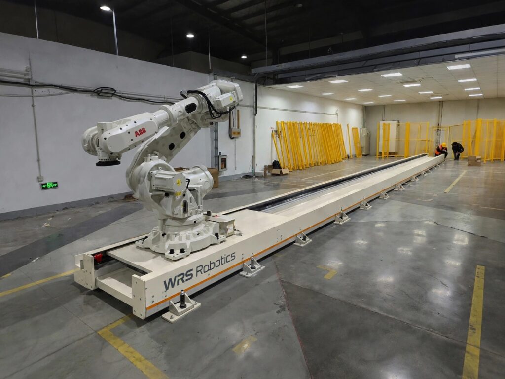
- The linear track. Many heavy-duty cells put the robot on a robot linear track so one robot can serve a long positioner, or two positioners in sequence. If the cell will grow to a second station, plan the track now — adding it later costs more than building it in.
- Cables and dress pack. The welding cables, the positioner cables, and the robot dress pack all have to move without tangling or pulling. A positioner that rotates 360 degrees needs cable management designed for it, not added afterwards.
The five selection mistakes we see most often
1. Sizing by weight alone. The catalogue rating is not a guarantee for any workpiece of that weight. The center of gravity offset and the moment of inertia decide the real torque. Send the drawing.
2. Forgetting the fixture. The fixture, the clamps, and the backing bars all ride on the positioner. Add them to the workpiece weight before you size anything.
3. Buying for today’s part only. A new variant, a heavier design revision, or a second product on the same cell can push a positioner over its rating within a year. Leave margin, and tell the supplier what might change.
4. Ignoring the worst weld. It is easy to check the easy seams and forget the one seam that needs the deepest tilt or the longest reach. That one seam decides whether the cell works.
5. Choosing the cheapest drive. A variable-speed axis is cheaper than a servo axis, until the cell needs coordinated motion and cannot have it. Decide based on whether the positioner moves during the arc, not on the price difference.
Selection checklist
Use this before you request a quotation. If you can answer every line, the supplier can size the positioner correctly the first time.
- Workpiece weight, including fixture, clamps, and backing bars
- Workpiece dimensions: length, width, height
- Center of gravity position, and its distance from the rotation axis
- Workpiece shape and a drawing or photo, if available
- Number of axes needed: 1, 2, or 3 — based on how many times the part must be re-clamped
- Positioner type matched to the shape: headstock–tailstock, L-type, C-type, U-type, platform, or S-type
- Drive type: servo (coordinated motion during welding) or variable-speed (indexing between welds)
- Required tilt range and rotation range for every production weld
- Required rotation speed range, especially the lowest stable speed
- Robot model and reach, checked at the worst positioner angle
- Floor space, crane access, and foundation for the positioner
- Future parts: heavier variants or a second product on the same cell
Our robot track questionnaire asks the same kind of questions for linear tracks — travel, payload, robot model, environment, accuracy, speed — because the sizing logic is the same: start from the real workpiece and the real cell, not from a catalogue headline.
FAQ
What size welding positioner do I need for a 1,000 kg workpiece?
Start with the total load — workpiece plus fixture — and then check the center of gravity offset. A compact 1,000 kg part close to the rotation axis is a straightforward 1-tonne machine. The same weight with the center of gravity 300 mm off the axis can need a machine rated well above 1,000 kg. Send the drawing and the center of gravity position, and size from the torque, not just the weight.
Is a two-axis positioner enough for heavy-duty welding?
For most heavy fabrication, yes. A two-axis machine — tilt plus rotation — brings nearly every weld into the downhand position. You need a third axis when the part must be welded on several faces in one setup, or when a long part needs two synchronized supports. Count the re-clamping operations: if two axes bring that number to zero, two axes are enough.
What is the difference between a headstock–tailstock positioner and an L-type positioner?
A headstock–tailstock machine holds a long workpiece between two ends and rotates it around its long axis. It suits beams, booms, chassis, and pressure vessels. An L-type machine mounts a compact, heavy part on a tilting table. It suits brackets, housings, and machine frames. The workpiece shape decides which one fits.
Do I need a servo positioner, or is variable speed enough?
If the positioner moves while the arc is on — for example, rotating a pipe during a circumferential weld — you need a servo axis coordinated with the robot. If the positioner only moves between welds, to bring the next seam into position, a variable-speed axis is enough and costs less.
Can one positioner handle different workpieces?
Yes, within limits. A positioner sized for your heaviest part with the largest center of gravity offset can usually handle lighter parts too, as long as the fixture can hold them. The limit is the heaviest and most eccentric part, not the average one. If a future part is heavier or more awkward than today’s, size for that part.
How do I know if my positioner is undersized?
The signs are consistent: the drive stalls or struggles at certain angles, the part creeps or drifts when tilted, circumferential welds show ripples, or the gearbox wears out far sooner than expected. If you see any of these, check the real load — workpiece plus fixture — against the rating, and check the center of gravity offset. An undersized positioner is a sizing problem, and re-teaching the robot will not fix it.
We are planning a new welding cell. What information should we send for a quotation?
Workpiece weight and dimensions, a drawing or photo, the center of gravity position, the robot model, the list of welds and the positions they need, and the floor space available. With that, a supplier can recommend the type, the axis count, and the drive — and the quotation will be for the machine your cell actually needs. Our welding positioner range covers single-axis, two-axis, and three-axis models, from compact tables to headstock–tailstock machines for long, heavy workpieces. If the cell also needs a longer robot reach, our guide to choosing the right robot positioner covers size, load, and axis selection in more detail.
The bottom line
A welding positioner is not bought by weight. It is bought by torque, by center of gravity, by workpiece shape, and by which welds need to be downhand. Get those four things right and the selection is straightforward. Get them wrong and the cell will fight you every day — slow loading, bad weld positions, and a drive that wears out early.
If you are sizing a positioner for a heavy workpiece, send us the details: workpiece weight and dimensions, the center of gravity position, the robot model, and the welds you need to make. We will help you work out the type, the axis count, and the drive your cell needs — before you spend money on the wrong machine. You can reach us at info@wrsrobotics.com or through the contact form on our welding positioner page.