
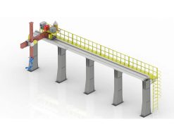
 Robot Linear track
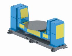 Robot welding Positioner
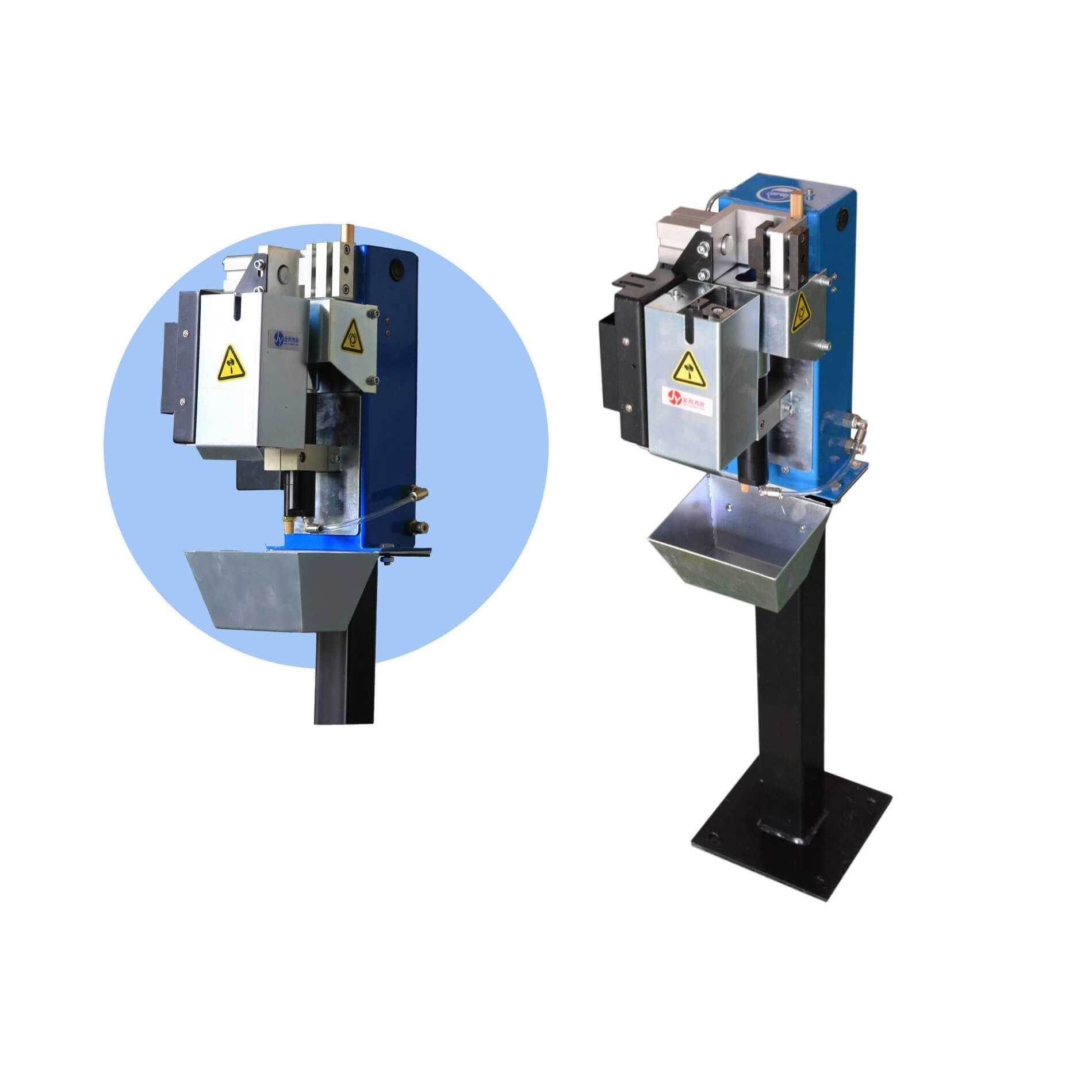 Robot Torch cleaning station
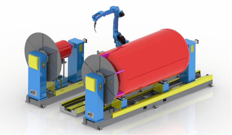 Welding Robot Workstations & Automation Solutions
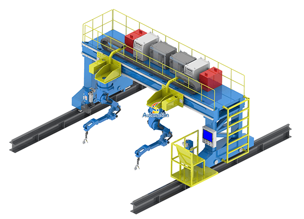 Robot Gantry System
Nobody calls us when the track works.
The phone rings when a welding cell that passed its acceptance test starts drifting out of tolerance three months later. It rings when a robot throws a following-error alarm halfway down the rail and the whole line stops at two in the morning. It rings when a maintenance lead says, flatly: “The track was accurate at installation, but it drifted” — and wants to know whether the track is bad or the install was.
Nine times out of ten, it’s the install.
A modern 7th-axis robot linear track is not a crude conveyor. The units we build repeat to ±0.1 mm and drive the slider at up to 1 m/s. But that number on the datasheet is a promise the installation has to keep. The rails, the helical rack, the slider, the servo — they only deliver ±0.1 mm if the foundation is right, the rails are parallel, the pinion mesh is set, the robot is mounted correctly, the cables survive the full travel stroke, the rails stay lubricated, and the robot controller knows what it’s driving. Get any one of those wrong and accuracy leaks away quietly. You won’t see it on day one. You’ll see it in rework, in weld defects, in alarms, in a cell that never quite hits its cycle time.
This article is built from the calls we actually get. Each mistake starts with the pain — what the customer felt on the shop floor — then what was mechanically going wrong, then how to avoid it. If you’re planning a track installation, or troubleshooting one that’s already running, start here.
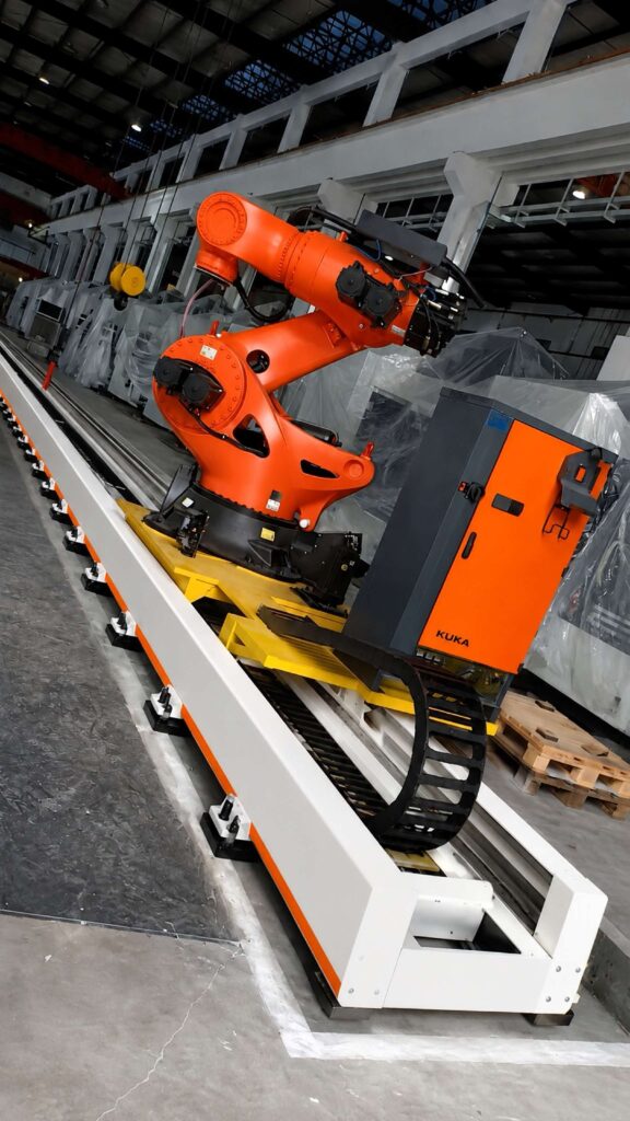
Mistake 1: Bolting the Rail to a Floor That Was Never Flat
The pain: “It was accurate at installation. Six months later the far end is off, and our welds don’t land where the program says.”
This is the single most common story we hear, and it almost never starts with the track. It starts with the floor. A workshop concrete slab is not a machine bed. It curls as it cures, it creeps under sustained load, and it takes a beating from forklift traffic and the general vibration of a working shop. When you bolt a precision rail straight to that slab and shim it level on day one, you’ve built a good-looking installation on a moving target.
Here’s what happens mechanically. A long track ships in standard 3.0 m (or 4.0 m) sections. If the slab under one section joint settles even 0.15–0.2 mm, you get a shallow dip exactly where two sections meet. The slider crosses that dip thousands of times a day, hammering the guide-rail raceways at the same spot every cycle. Over weeks that turns into brinell marks — tiny dents in the raceway — and the rail’s straightness is gone. The cruel part: the acceptance check passed, because the dip hadn’t formed yet. The drift shows up first at the far end of travel, exactly where long weld seams need the accuracy most.
How to avoid it. Don’t level the track to the floor; level the track to itself, on a foundation that doesn’t move. The proven setup is a welded steel foundation frame (or machined sole plates) on adjustable anchor bolts and leveling wedges — which is how our tracks ship as standard. Set the frame, level the rail sections to each other with a precision level along the full travel, then grout. And don’t walk away: re-check the level after roughly a month of production, once the foundation has taken its set, and record the readings so the next check means something. A track that holds its level holds its accuracy.
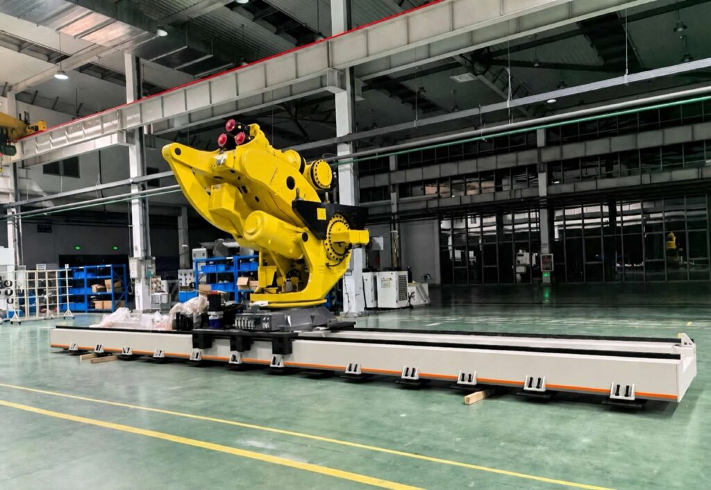
Mistake 2: Aligning Two Rails by Eye Instead of by Instrument
The pain: “The servo keeps alarming, the guides are wearing unevenly, and we’ve had to slow the whole cell down.”
A robot linear track runs the slider on two parallel guide rails, and “parallel” here is a measured quantity, not a visual impression. Nobody can eyeball parallelism over six or nine metres, but plenty of installs try — a straightedge here, a tape measure there, tightened down and called good.
The rack makes this unforgiving. On a rack-and-pinion track the rack is fixed to the bed between the two rails, so the pinion mesh is only as consistent as the rail alignment. If the rails converge or diverge along the travel, the mesh tightens at one end and loosens at the other. The slider starts to bind where it’s tight — servo current climbs, following-error alarms appear, and the integrator’s usual fix is to derate the speed, which is where your cycle time goes. Where it’s loose, you get the backlash problems of Mistake 3. Either way, the guides wear unevenly and the ±0.1 mm repeatability becomes a rumour.
How to avoid it. Sweep the rails with a dial indicator (or a laser tracker on long tracks) over the full travel before you call the alignment done. Tighten the bed bolts in sequence, from the centre outward, and stagger the rail joints between the two rails so no two joints line up. Verify first with the slider unloaded, then again with the robot mounted — the load changes things. Ten extra minutes with an indicator at this stage saves a week of troubleshooting later.
Mistake 3: Setting the Pinion–Rack Mesh by Feel
The pain: “It’s accurate moving left to right, but the return pass is off. Circles come out oval.”
Ask a welder how they found this one and they’ll point at a circular weld that isn’t circular. Direction-dependent error is the fingerprint of a rack-and-pinion mesh problem. The pinion has to engage the helical rack with a defined clearance — too tight and you get heat, wear, and a servo fighting friction; too loose and you get lost motion every time the axis reverses direction. “By feel” usually means too tight, because a tight mesh feels solid and precise when you tug it by hand. It isn’t. It’s just preloaded wear.
How to avoid it. Set the mesh to the manufacturer’s spec with a feeler gauge or pressure film — not your thumb. On axes that reverse constantly (weaving, circular interpolation), consider a spring-loaded or dual-pinion anti-backlash arrangement rather than a single rigid pinion. Grease the rack on a schedule, and in welding cells shield the whole drive with bellows or organ covers; spatter on the rack teeth is a mesh problem wearing a disguise. Then prove it: run a bidirectional positioning check — same target, approached from both directions, over the full stroke — before you sign off. If the two directions don’t agree, the mesh isn’t right yet.
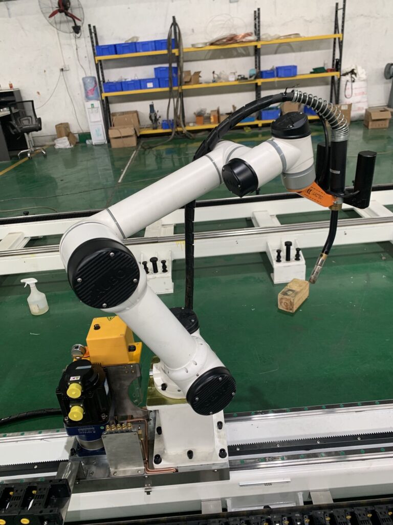
Mistake 4: Getting the Robot Mounting Interface Wrong
The pain: “The robot faults the moment the track moves — like it hit something.”
When a customer calls with this one, the first question we ask is what the slider is actually carrying. A robot linear track has two different load ratings and people mix them up constantly: the total slider load (on our enclosed 7th-axis unit, up to 2800 kg including the slider itself and everything bolted to it) and the end load at the robot mounting face (up to 300 kg). A six-axis arm that looks fine on paper can blow past the moment ratings once you add the wrist payload, the torch, the dress pack, and the reach envelope at full extension. Overhung load doesn’t just stress the servo — it deforms the linear guides microscopically, and the controller reads that deformation as a collision.
The mounting details matter as much as the numbers. The robot mounting height has to match the cell layout, the mounting plate has to be flat, and dowel pins — not just bolts — are what let you remove and remount the robot and land back in the same place. Our standard slider mounting face is 1200 × 720 mm, which fits the common robot base patterns, but “fits” isn’t “correct” until the flatness and pinning are verified.
How to avoid it. Send the robot model, the full payload stack (arm + tooling + dress), and the reach envelope before the track is sized — not after it arrives. Torque the mounting bolts in a star pattern and re-torque after the first week of thermal cycling; bolts settle. And do the servo tuning with the real payload mounted (see Mistake 7). A track that alarms with the robot on it and runs fine empty was never a track problem — it was a mounting and loading problem.
Mistake 5: Leaving the Drag Chain for Last
The pain: “Random cable faults. E-stops in the middle of a cycle, and nobody can reproduce them on demand.”
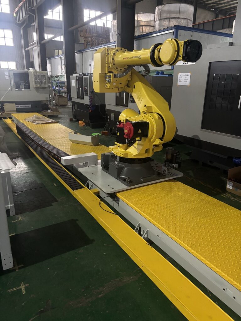
Cable management is the part of the layout everyone sketches last, and it’s where some of the nastiest downtime comes from. The drag chain’s position — left side or right side of the rail — decides the total installed width of the track (rail width including the drag chain), and if that wasn’t on the layout drawing, the chain ends up routed around something it was never meant to clear. Cables need a defined bend radius and enough length to cover the full travel stroke with a service loop to spare. Remember that on a track like our enclosed unit, the effective travel is the total length minus 1500 mm — the cable has to survive every millimetre of that, thousands of times a day.
The intermittent faults are the tell. A cable that only breaks contact at one end of travel, or only when the chain flexes a certain way, gives you alarms that vanish when the technician arrives. Worse, servo power and signal cables lashed together in one chain invite noise faults that look exactly like mechanical problems.
How to avoid it. Confirm the drag-chain side at order time, not on site — it changes the layout width. Reserve that width on the floor drawing and keep the chain’s path clear of guarding and fixtures. Separate power from signal, respect the bend radius, and before first power-on, walk the slider through the full stroke by hand and watch the chain. If it snags, rubs, or pulls tight anywhere, fix it now. Cables are cheap; the downtime they cause isn’t.
Mistake 6: Forgetting That Rails Need Oil and Spatter Needs Blocking
The pain: “My welds are off after a few months. The track was fine at commissioning.”
A welding cell is one of the most hostile places you can put a precision rail: weld spatter, grinding dust, and smoke, all day. An open rail in that environment is on borrowed time. The failure mode is slow and deniable — the raceways pick up contamination, wear accelerates, and the accuracy drifts a little every week until the welds stop landing. Then someone blames the robot, the program, or the fixture, and the rail gets checked last.
How to avoid it. First, keep the contaminants out: a fully enclosed track with sealing bellows or organ covers earns its keep in any welding or grinding cell. Second, keep the oil in: linear guides and racks need scheduled lubrication — our tracks run an automatic lubrication system on 46# guide-rail oil, but “automatic” doesn’t mean “fit and forget.” Commission the lube system on day one (we’ve seen tracks run dry for weeks because filling the reservoir was left for “later”), check the reservoir on a schedule, and wipe down and re-grease the rack before and after long shutdowns. Clean oil on clean steel is the cheapest accuracy insurance there is.
Mistake 7: Integrating the 7th Axis Into the Controller as an Afterthought
The pain: “The robot stops and alarms on the track. The robot supplier says it’s the track; the track supplier says it’s the robot.”
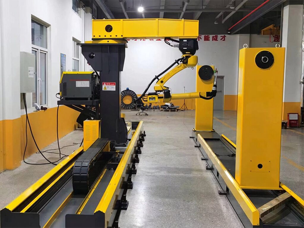
Everybody’s favourite finger-pointing exercise. Here’s the reality: the 7th axis is a coordinated robot axis, not a standalone slide. The servo motor and cable are normally supplied to match the robot brand — ABB, KUKA, FANUC, YASKAWA — so the axis can interpolate with the arm. But the tuning has to reflect the actual moving mass. An axis tuned empty and then loaded with a 2800 kg slider-plus-robot stack will oscillate, overshoot, and throw following errors; an axis tuned for full load and run empty can be just as unhappy. Wrong inertia parameters are the root cause of a depressing number of “track alarms.”
Then there’s the calibration layer: mastering the axis, setting the home position, and defining soft limits before the cell ever runs in auto. Skip those and the first person to jog the track to the hard stop in manual mode gets an education.
How to avoid it. Bring the robot integrator into the conversation before the mechanical install, not after. Tune the servo with the real payload mounted and tooled. Set soft limits inside the mechanical travel and verify them with a slow full-stroke program. And before handover, prove the repeat positioning accuracy the way it will be used: a dial indicator on the slider, same targets approached from both directions, full stroke, several cycles. ±0.1 mm on that test, both directions, is the only acceptance number that matters.
What a Clean Installation Actually Looks Like
None of the above is exotic. To show what “done right” looks like in practice, picture a typical heavy welding cell: a six-axis robot riding a 9-metre enclosed 7th-axis track, welding long structural parts that need consistent seams over the full travel.
The buyer sent everything needed for a proper quotation up front: the robot model, the slider payload, the rail travel stroke and total length they wanted, the operating environment (indoor, welding spatter), the rail width including the drag chain for their floor layout, the robot mounting height, their preferred guide-rail brand, the drag-chain position, the lubrication arrangement, the servo motor and cable setup, and the paint colour — RAL5015 blue is the standard. Because the track left the factory pre-assembled and aligned in 3.0 m sections, the site work was mechanical assembly, not discovery: set the foundation frame, level, grout, align the sections, set the rack mesh, route the drag chain, fill the auto-lube reservoir. The integrator tuned the axis with the robot mounted and tooled, ran the bidirectional accuracy check, and the handover numbers matched the re-check a month later.
That job had no drama in it, which is exactly the point. Accuracy problems are almost never a mystery of the hardware. They’re a skipped step, in the wrong order, found months later. Do the steps in order and there’s nothing to find.
Robot Linear Track Installation Checklist
Tape this to the panel door. It’s the short version of everything above.
- Before you order: robot model, full payload stack, required travel stroke and total length, operating environment (indoor 5–40 °C, outdoor −20 to +50 °C), rail width including drag chain, robot mounting height, guide-rail brand preference, drag-chain side, lubrication setup, servo motor and cable arrangement, paint RAL code.
- Foundation: welded steel frame or sole plates on adjustable anchor bolts and leveling wedges; level rail sections to each other over full travel; grout; record the readings.
- Mechanical: sweep rail parallelism with an indicator; stagger rail joints; tighten bed bolts centre-out; set pinion–rack mesh to spec; confirm bellows/covers fitted.
- Robot mounting: verify plate flatness and dowel pins; torque in star pattern; re-torque after one week; confirm total and moment loads against ratings.
- Cables: drag-chain side as ordered; bend radius respected; power separated from signal; full stroke walked by hand before power-on.
- Lubrication: auto-lube reservoir filled and commissioned; schedule posted; rack wiped and greased.
- Controls: servo matched to robot brand and tuned with real payload; axis mastered; soft limits set and verified; bidirectional repeatability proven with an indicator.
- After one month: re-check level, re-torque mounting bolts, inspect raceways and rack, confirm the accuracy check still passes.
FAQ: The Questions We Actually Get Asked
My track was accurate at installation but drifted after a few months. What happened?
Start with the foundation, not the track. Re-check the rail level over the full travel against your commissioning readings — slab creep and settlement are the usual suspects. Then inspect the guide-rail raceways for brinell marks or contamination wear, and check the lubrication system actually has oil in it. In our experience the order of likelihood is: foundation movement, contamination, dry rails, and only then a mechanical fault in the track itself.
My welds are off after a few months — is it the track or the robot?
Isolate them. Put a dial indicator on the slider and run a bidirectional repeatability check on the track alone — if the track repeats to spec, look at the robot: TCP calibration, wrist backlash, fixture wear. If the track doesn’t repeat, work through Mistakes 1, 2, 3 and 6 above. Welds are just the messenger; don’t shoot them.
The robot stops / alarms on the track — where do I start?
Check the cheap things first: drag-chain cables (intermittent faults love cable chains), then the controller — payload and inertia data entered correctly, servo tuned with the real load, soft limits set. Mechanical binding from alignment or mesh problems usually shows up as rising servo current before it becomes an alarm, so the drive’s current log is worth reading.
I don’t know what dimensions and loads to send for a quotation — what do you need?
This is the most useful question on the list, because getting it right up front prevents half the mistakes above. Send us: the robot model; the slider payload (robot + tooling + dress pack); the rail travel stroke and total length you need; the operating environment; the rail width including the drag chain for your layout; the robot mounting height; your preferred guide-rail brand; the drag-chain position (left or right); the lubrication arrangement; the servo motor and cable setup; and the paint RAL code. With that, we can size the track, the slider, and the drive correctly the first time. For background reading, our complete guide to robot linear tracks walks through the options.
Can a 7th-axis track run outdoors?
Yes, with the right specification. Our tracks are rated −20 to +50 °C for outdoor duty (5–40 °C indoors), but outdoor installation needs the enclosed design, proper covers over the rails and rack, and attention to drainage so the foundation frame doesn’t sit in water. Tell us it’s outdoor at quotation stage — retrofitting weather protection is never as good.
Final Word: Buy the Track, Then Protect the ±0.1 mm
A robot linear track is one of those purchases where the hardware is only half the job. The other half is everything in this article: the foundation, the alignment, the mesh, the mounting, the cables, the oil, and the controller integration. Get those right and a good track holds its accuracy for years. Get them wrong and even the best hardware in the world becomes a very expensive lesson in rework.
That’s how we build our tracks at WRS Robotics — to make the installer’s job easier, not harder. Our fully enclosed 7th-axis robot linear track ships with a welded steel foundation frame, anchor bolts and leveling wedges as standard, a helical gear-and-rack drive with a precision planetary reducer, automatic 46# guide-rail oil lubrication, and servo packages matched to ABB, KUKA, FANUC and YASKAWA controllers — repeating to ±0.1 mm at up to 1 m/s slider speed. For heavier gantries, our 3000 kg 7th-axis robot transfer unit covers the big payloads, and it pairs well with our servo welding positioners for full multi-axis cells.
If you’re planning a track — or troubleshooting one — send us the robot model and the numbers from the checklist above. We’ll help you get the installation right the first time, so the accuracy you paid for is the accuracy you keep.