
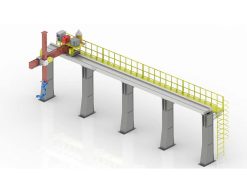
 Robot Linear track
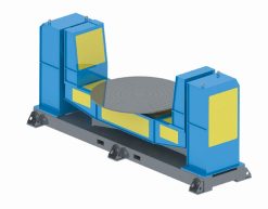 Robot welding Positioner
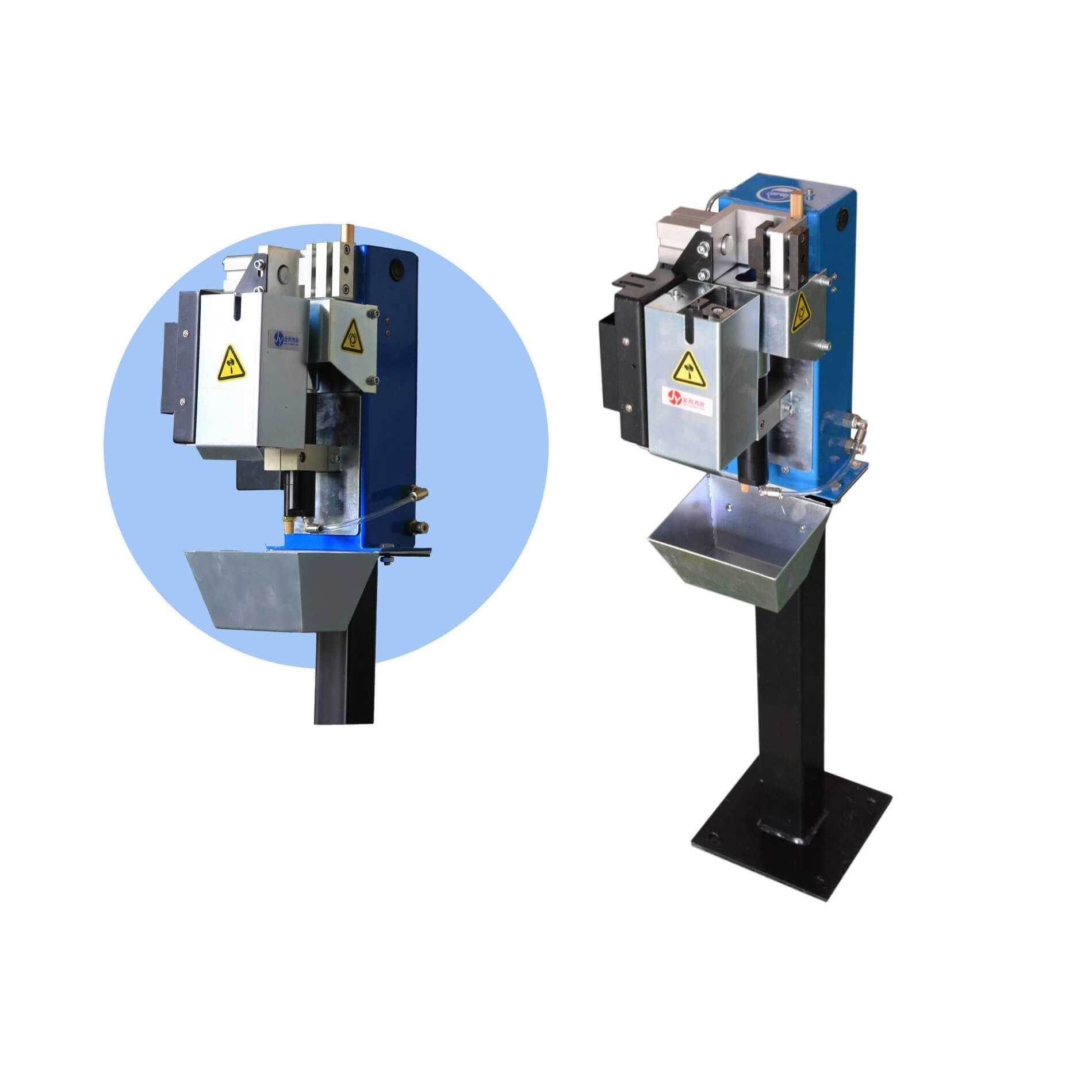 Robot Torch cleaning station
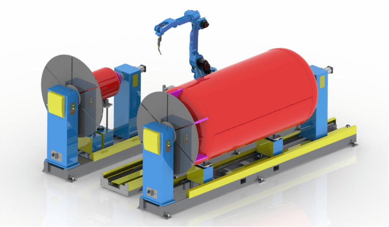 Welding Robot Workstations & Automation Solutions
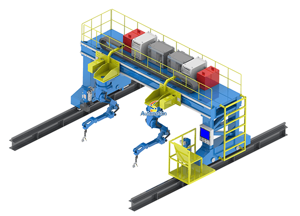 Robot Gantry System
The phone call every positioner supplier gets
It usually goes like this. A customer calls and says the positioner cannot tilt their part. The positioner is rated for 2,000 kg. The part weighs 800 kg. The fixture, maybe another 150. So the total is under half the rated load, and yet the tilt axis faults out halfway up, or creeps, or holds fine at the bottom and then slips as the table comes level. The customer is understandably annoyed. The positioner is not broken. The catalogue number just never meant what they thought it meant.
A rated load on a welding positioner is measured with the load’s centre of gravity sitting on the rotation axis. That is the condition the number assumes. Move the centre of gravity away from the axis — which is what happens with almost every real weldment — and the drive no longer just holds weight. It fights gravity, and gravity has a lever arm.
This article explains that lever arm: how to calculate the torque your positioner actually needs, why a part well under the rated load can still be too much, and what to measure before you order so the machine you buy can move the part you actually weld.
What the catalogue number actually means
When a positioner is rated at 1,000 kg, or 2,000, or 5,000, that number describes a balanced load. The workpiece sits centred on the table, its centre of gravity on the tilt axis and on the spin axis, and the drives see little more than the weight itself and the inertia when they accelerate.
Real workpieces are rarely balanced. A steel frame is heavier at one end. A pressure-vessel head sits high above the table. A long beam is clamped off-centre because that is where the fixture could grip it. A weldment with a flange on one side and nothing on the other has its centre of gravity somewhere the drawing never marked. In each case the centre of gravity sits some distance from the axis, and that distance is what the drive feels.
There is a second number people forget: the fixture. The rated load has to carry the fixture as well as the workpiece. A heavy steel fixture with clamps and locating blocks can easily add 10 to 30 percent to the moving mass, and every kilogram of it sits at whatever distance from the axis the fixture design put it. We ask customers for the workpiece weight and then ask, separately, for the fixture weight, because the second number is the one that usually arrives late — after the positioner has been sized.
The one formula that matters
The static torque the tilt axis has to hold is simple:
T = m × g × e
T is the torque in newton-metres. m is the total moving mass in kilograms — workpiece plus fixture plus clamps. g is 9.81. e is the horizontal distance, in metres, between the centre of gravity and the tilt axis.
Take a real example. A weldment weighs 800 kg. The fixture weighs 150 kg. Total moving mass is 950 kg. The centre of gravity sits 250 mm off the tilt axis — not an unusual number for a frame that is clamped to one side of the table. The holding torque is 950 × 9.81 × 0.25, which is about 2,330 N·m.
That is the torque just to hold the part still, at the worst angle, before anything moves. Drives are not sized on holding torque alone. A safety factor is applied for friction, for wear, for the day the next part is slightly heavier than this one. A factor of 1.5 is common practice, which brings the requirement to roughly 3,500 N·m. If the positioner’s tilt drive is rated at 3,000 N·m, this setup is undersized — even though 950 kg is less than half of a 2,000 kg rated load. That is the whole story in one calculation: the load rating and the torque rating are two different limits, and the torque limit is usually the one that bites first.
Now move the same part 150 mm closer to the axis, so the centre of gravity sits 100 mm off it. The torque becomes 950 × 9.81 × 0.10, about 930 N·m. With the same safety factor, the requirement is roughly 1,400 N·m — comfortable for the same drive. Nothing about the part changed. The mounting position did, and the torque requirement more than halved. This is why we spend so much time on fixture layout before we talk about drive sizes.
The tilt axis and the rotate axis are two different problems
A two-axis positioner has two drives, and the centre of gravity loads them differently.
The tilt axis is the one doing the visible work. Its worst case is when the table is horizontal and the centre of gravity is at its maximum horizontal distance from the axis — that is when gravity has the longest lever arm. As the table tilts toward vertical, the lever arm shortens, and the torque falls. So the tilt drive is sized on the horizontal position, with the part at its worst offset.
The rotate axis — the spin axis — has a different worst case. When the table is flat, the spin axis is vertical, gravity acts straight down it, and the drive sees almost no gravity torque at all. Tilt the table to 90 degrees and the spin axis is horizontal, and now any offset between the centre of gravity and the spin axis becomes a gravity torque on that drive too. A part that spins happily when flat can stall the rotate drive when tilted, and the fault will look like a servo problem when it is actually a geometry problem. Both axes need the same calculation, with the centre of gravity measured against each axis separately.
On a headstock-tailstock positioner the same thinking applies, with the rotation axis running through the two headstocks. The workpiece hangs between them, and its centre of gravity is usually below the axis or off to one side. The torque the headstock drive must hold is again mass times gravity times the offset — and on a long part, a small offset at the middle becomes a large deflection at the ends, which is a welding accuracy problem as much as a drive problem. Our article comparing headstock-tailstock and turntable positioners for pipe welding goes into the layout side of that choice.
Moving is harder than holding
So far everything has been static — holding a part still. Moving it needs more.
To tilt a part, the drive has to accelerate its mass. The resistance to acceleration is the moment of inertia, and inertia grows with the square of the distance from the axis. Double the offset and the inertia roughly quadruples. That is why a heavy part mounted far from the axis is slow to start, overshoots when it stops, and faults on acceleration even when it holds perfectly still at rest. The fix is usually not a bigger motor. It is a slower tilt speed, a longer ramp time, or a better mounting position. In practice, heavy eccentric parts are tilted slowly, and anyone who tries to tilt them fast learns why within a week.
There is also the brake. When power is off, or when the servo faults, the brake has to hold the same gravity torque. A brake sized for a balanced load can slip under an eccentric one, and a slipping brake on a tilted table is how parts get damaged. Brake holding torque belongs in the same calculation as drive torque, and it is the item most often left out of it.
What actually breaks when the torque is wrong
When a positioner is undersized for its real torque load, the failure rarely announces itself as “undersized.” It shows up as other problems, and it gets chased as other problems.
The most common is servo faults on the tilt axis — over-torque alarms that appear only at certain angles, only with certain parts, and never on the test piece the supplier used. Then there is uneven wear: a gearbox that was supposed to last years develops backlash early, because it has been working against a gravity load in one direction on every cycle. Slew bearings wear unevenly under eccentric load, and their rated life falls fast once the load stops being centred.
And then there is accuracy. Torque bends structure. A table that deflects a fraction of a degree under an offset load moves the weld by millimetres at the far end of a long part. The robot program was taught on an empty or balanced table, the real part sits differently, and the weld misses the seam. That gets investigated as a robot calibration issue — we wrote about why external axis calibration fails — when the cause is the positioner flexing under a load it was never calculated for. If your welds drift between the first part and the tenth, or between a light part and a heavy one, check the torque calculation before you touch the robot program.
How to calculate it before you order
You do not need simulation software for a first answer. You need four numbers, and a tape measure will get you three of them.
First, the total moving mass: workpiece, fixture, clamps, and anything else bolted to the table. Weigh the fixture if you can. If you cannot, estimate it honestly — a steel fixture for a 1,000 kg part is rarely under 100 kg.
Second, the centre of gravity. For a simple part, it can be estimated from the drawings. For a weldment, the honest answer is often “we don’t know exactly,” and that is fine — calculate with the worst case, the furthest the centre of gravity could plausibly sit from the axis. If the part is asymmetric, assume the offset is larger than you think. The cost of overestimating here is a slightly larger drive. The cost of underestimating is a positioner that cannot tilt the part.
Third, the offsets: the distance from the centre of gravity to the tilt axis, and to the rotate axis, in the mounting position you actually intend to use. Measure it on the fixture, not on the drawing. Fixtures move parts by 50 mm without anyone noticing.
Fourth, the motion: how fast the table has to tilt and rotate, and how many cycles per shift. Speed and duty cycle decide the dynamic torque and the wear. A positioner that tilts twice a day can live with a marginal torque number. One that tilts every ninety seconds cannot.
Run the formula for the tilt axis at the horizontal position, and for the rotate axis at maximum tilt. Apply a safety factor of 1.5 as a minimum. Compare the result with the drive’s rated torque, not with the positioner’s load rating. If the numbers are close, the mounting position needs to change, or the drive needs to go up a size. This is the calculation we do for every positioner inquiry before we quote — it is also the set of questions in our sizing questionnaire, because the answers change the machine. Our guide to choosing a welding positioner for heavy-duty robotic welding covers the rest of the selection, and our article on calculating payload for a robot linear track covers the same kind of thinking on the track side, where the load rating and the real load also part company.
When the number comes out too big
A torque requirement that exceeds the drive is not the end of the conversation. It is usually fixable, and the fixes are cheaper before the positioner is built than after.
The first fix is the mounting position. Move the part closer to the axis, rework the fixture so the centre of gravity sits nearer the centre of the table, or flip the part so its heavy end is near the axis. We have seen 150 mm of repositioning cut a torque requirement in half, as in the example above. Fixture design is part of positioner sizing, not an afterthought to it.
The second is a counterweight. It sounds crude, and it works: a block on the opposite side of the axis balances the offset, at the cost of added mass. It is a legitimate solution when the part cannot be repositioned, though it adds inertia, so it is not free.
The third is speed. Slow the tilt down, lengthen the ramp, and the dynamic torque falls. This costs cycle time, so it is a trade-off, not a fix — but for a low-volume heavy part, a slower tilt is often the right trade.
The fourth is the drive itself: a larger servo, a bigger gearbox, a stronger brake. This is the honest answer when the part is simply heavy and offset and nothing else can change. It costs more, and it is still cheaper than a positioner that cannot do its job.
And sometimes the answer is a different positioner type altogether. A part that is badly eccentric on a single-axis turntable may be comfortable on a two-axis L-type or a headstock-tailstock setup where the geometry works with the load instead of against it. That is a selection decision, and it is why the torque calculation comes before the model selection, not after it. If you are weighing types, our positioner selection article sets out the axis choices.

A torque checklist
Before you order a welding positioner, work through this list. If you cannot answer an item, that is the item to resolve first.
- Total moving mass. Workpiece plus fixture plus clamps — weighed or honestly estimated, not the workpiece alone.
- Centre of gravity, in three dimensions. From the drawings, or a worst-case estimate if the weldment is asymmetric.
- Offset from the tilt axis. Measured on the fixture in the real mounting position, at the worst angle.
- Offset from the rotate axis. Same measurement, against the second axis.
- Static tilt torque. m × g × e at the horizontal position, with a safety factor of at least 1.5.
- Rotate-axis torque at maximum tilt. The second calculation, not an afterthought.
- Dynamic torque. Tilt and rotate speeds, ramp times, and the inertia of an offset load.
- Brake holding torque. The brake must hold the same gravity torque with the power off.
- Bearing and gearbox loading. Eccentric loads wear unevenly; check the ratings under offset, not centred, load.
- Table deflection. What a fraction of a degree at the table means in millimetres at the weld.
- Fixture layout. Can the part be mounted closer to the axis, or counterweighted?
- The next part. Will a heavier or more offset workpiece arrive next year? Size for it now if it will.
FAQ
What is eccentric load on a welding positioner?
It is any load whose centre of gravity does not sit on the positioner’s rotation axis. Almost every real weldment is eccentric to some degree, because parts are asymmetric and fixtures grip them where they can. The offset creates a gravity torque the drives must overcome, and that torque — not the weight alone — is usually what limits the positioner.
Why does my positioner struggle with a part lighter than its rated load?
Because the rated load assumes a balanced load with its centre of gravity on the axis. A lighter part mounted off-centre can demand more torque than a heavier balanced part. Calculate m × g × e for your actual mounting position and compare it with the drive’s torque rating, not the load rating.
How do I find the centre of gravity of a weldment?
From the CAD model, if you have one — most CAD systems report it directly. Without CAD, estimate it from the drawings by breaking the part into simple shapes, or calculate the worst case: the furthest the centre of gravity could sit from the axis. When in doubt, assume a larger offset than you think. The cost of overestimating is a bigger drive; the cost of underestimating is a positioner that stalls.
What safety factor should I use for tilt torque?
A factor of 1.5 on the static holding torque is common practice as a minimum. Use more if the part varies, if the fixture is heavy, or if the positioner will tilt frequently. The safety factor covers friction, wear, and the next part being slightly heavier than this one.
Does the fixture weight count toward the load?
Yes — all of it. The fixture, the clamps, the locating blocks, and anything else bolted to the table are moving mass, and they sit at whatever distance from the axis the fixture puts them. A steel fixture can add 10 to 30 percent to the total, and it is the number most often left out of the calculation.
Can a counterweight fix an eccentric load problem?
It can, and it is a legitimate solution when the part cannot be repositioned. A weight on the opposite side of the axis balances the offset and cuts the gravity torque. It adds total mass and inertia, so the tilt speed usually has to come down, but for a heavy part that cannot be mounted any closer to the axis, it is often the cheapest answer.
What to send us before you order
The fastest way to a positioner that fits is to send us the numbers this article asks for: the workpiece weight and dimensions, the fixture weight if you know it, the centre of gravity if your drawings show it, the robot model it will work with, and how fast the table needs to tilt and rotate. A photo of the part on its current fixture helps more than a paragraph of description — it shows us where the weight actually sits. Tell us the heaviest part the cell will ever weld, not just the one it welds today, and we will tell you the torque the drives need, whether the mounting position can be improved, and which positioner type fits.
You can reach our engineering team through the contact page, or browse our welding positioner range, our robot linear track range, and our gantry system range to see the equipment we build.
By WRS Robotics Engineering Team