
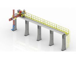
 Robot Linear track
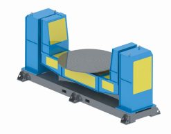 Robot welding Positioner
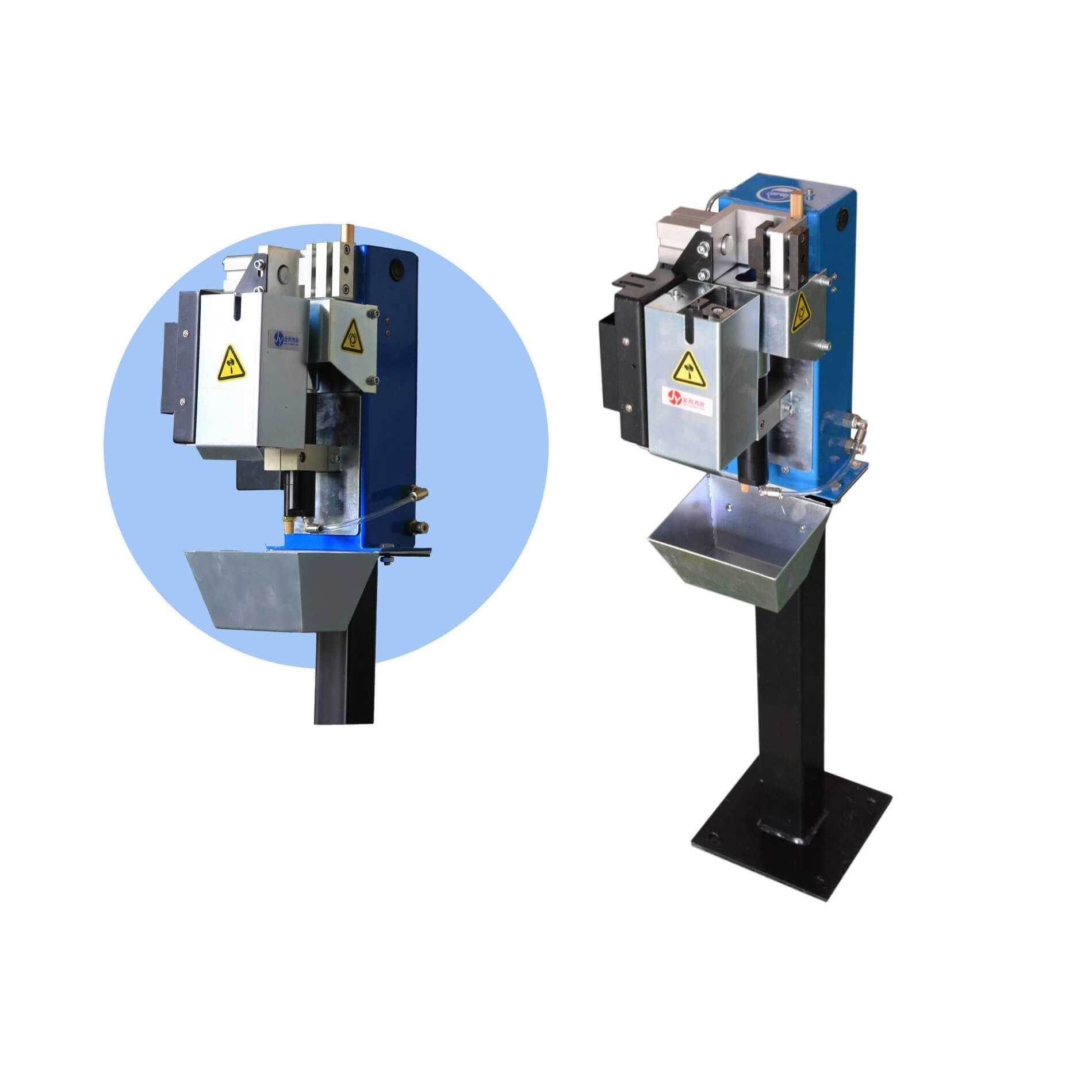 Robot Torch cleaning station
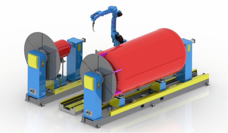 Welding Robot Workstations & Automation Solutions
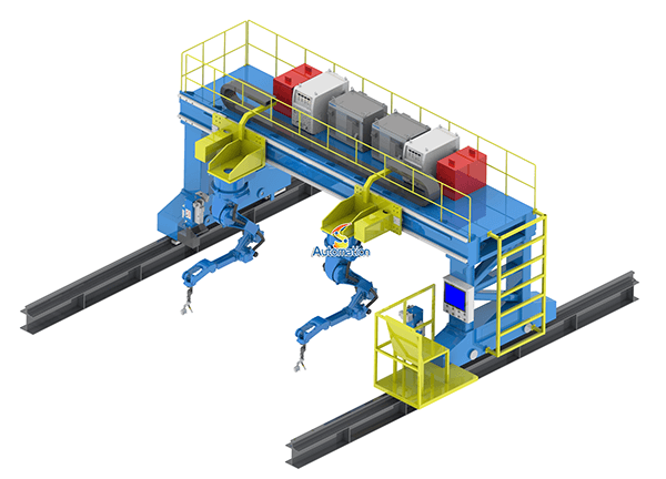 Robot Gantry System
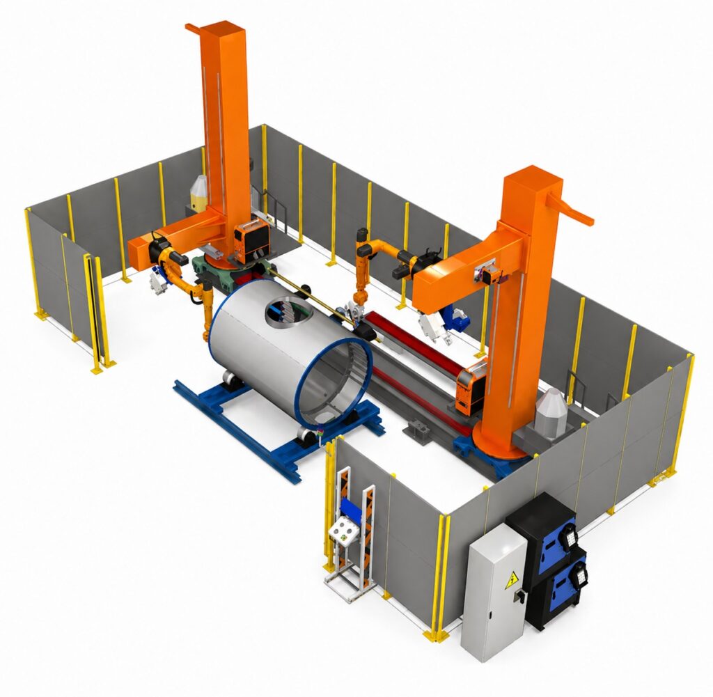
The cell is mechanically finished. The track is bolted down and level, the positioner is wired, the robot is taught, and the fence is up. You press cycle start — and nothing moves. Or the wrong thing moves. Or the robot strikes an arc while the positioner is still turning, and the weld lands a centimetre from the seam. The mechanics are fine. The machines just aren’t talking to each other properly.
That is the most common commissioning problem we see on robotic welding cells, and it has almost nothing to do with the track or the positioner as hardware. A modern welding cell has at least three controllers in it: the robot controller, the PLC that runs the cell, and the drives that move the external axes. Each of them is doing its own job correctly. The failures happen in the gaps between them — a signal that was never defined, a handshake that never completes, a safety input wired as if it were an ordinary one. This article walks through the seven communication problems we run into most often, what they look like on the shop floor, and how to fix each one.
Three controllers, one cell — who is actually in charge?
Before any of the specific problems make sense, it helps to be clear about who owns what. In most robotic welding cells the robot controller owns the robot and its external axes — the track and the positioner are configured as additional axes of the robot, so the robot program commands them directly and they move in coordinated motion with the arm. The PLC owns everything around that: the cell sequence, the fixture clamps, the part-present sensors, the torch cleaning station, the operator interface, and the safety system.
So the two controllers need a constant conversation. The PLC tells the robot which program to run and when to start. The robot tells the PLC when it is done, and whether the weld succeeded. The PLC tells the positioner — through the robot, or directly — to index to the next side, and waits for confirmation before it lets the robot move again. When that conversation is designed properly, the cell runs for a shift without anyone touching it. When it isn’t, the cell stops every twenty minutes and someone has to walk over and reset something.
The other architecture worth knowing is the PLC-as-master layout, where the PLC commands the external axis drives directly and the robot is essentially a guest in the cell. It works, and some integrators prefer it, but it has a real cost: the track and positioner can no longer move in true coordinated motion with the robot, because the robot controller doesn’t own them. For welding, where the torch angle relative to a moving workpiece is the whole point, that usually matters. Whatever architecture you choose, the important thing is that someone writes it down before the hardware is ordered. Most communication problems start as an assumption that was never written down.
1. The fieldbus mismatch — machines that speak different languages
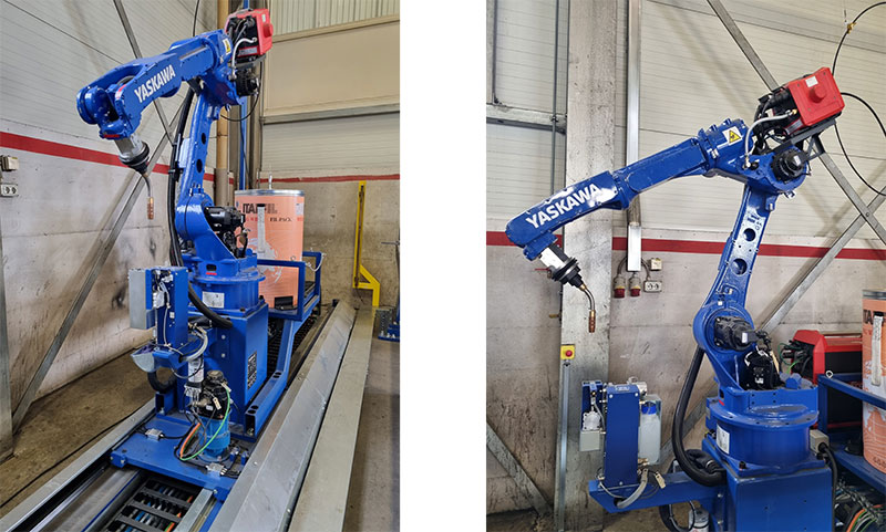
The first problem is also the most basic: the PLC and the robot controller don’t share a fieldbus. Siemens PLCs speak Profinet. Rockwell speaks EtherNet/IP. Beckhoff speaks EtherCAT. Mitsubishi leans on CC-Link. A FANUC, ABB, KUKA or Yaskawa robot can speak most of these — but only if the right option package was ordered with the robot. A robot delivered without the Profinet option cannot talk to a Siemens PLC, and no amount of programming will fix that. The option has to be bought, licensed, and installed, which takes days and costs money that nobody budgeted.
We see this most often when the robot, the PLC and the external axes come from three different suppliers and each one assumed the others would adapt. The fix is unglamorous: specify the fieldbus in the request for quotation, by name, and get written confirmation that every controller in the cell supports it — robot, PLC, positioner drives, and any remote I/O. If two devices genuinely can’t share a bus, a gateway can translate between them, but treat that as a last resort. A gateway adds latency and a single point of failure, and it becomes the first thing everyone blames when the cell behaves strangely.
2. The handshake that never happens
Fieldbus connected, both sides powered, and still nothing moves. The usual cause is a handshake that was never fully defined. A cell sequence is a chain of handshakes: the PLC requests a positioner move, the positioner confirms it is in position, the PLC releases the robot, the robot confirms the weld is done, the PLC indexes the table. Every step needs a request signal and a confirmation signal, and every confirmation needs a timeout with an alarm.
What actually happens in a rushed integration is that half of those pairs exist. The PLC sends “move positioner” and then simply waits a fixed three seconds before releasing the robot, because nobody wired the “in position” signal back. That works until the day the positioner is carrying a heavier part, or the table is cold, and the move takes four seconds. The robot starts welding while the table is still turning. Or the reverse: the robot finishes a weld and sets “cycle done,” the PLC never sees it because the signal was mapped to the wrong bit, and the cell sits there with the operator wondering why it stopped.
The fix is a signal list that both sides sign off on before programming starts — every signal, its direction, its meaning, and what happens if it doesn’t arrive. Each handshake gets a timeout. And “in position” should mean the axis has arrived and settled, not just that the move command was issued. A drive that reports “command complete” the moment it starts moving is telling you almost nothing.
3. I/O mapping errors — the signal is there, in the wrong place
This one is quiet and expensive. The wiring is right, the fieldbus is up, the signal list exists — and the positioner still goes to the wrong place, or the track overshoots by a fixed amount on every cycle. Somewhere in the mapping, a signal landed on the wrong bit.
The usual suspects are small and easy to miss. Byte offsets that start at 0 on one side and 1 on the other. A 32-bit position value read as two 16-bit words in the wrong order. A signed integer interpreted as unsigned, so a negative offset becomes an enormous positive one. A raw encoder count arriving at the PLC with nobody applying the scale factor that turns counts into millimetres. We have seen a track commanded to move 2,500 mm arrive at 25 mm because the value was scaled by 100 on one side and not the other — and the only reason it didn’t crash into the end stop is that the software limits caught it first.
The fix is boring and it works: test every signal one by one at commissioning, from the real device to the real screen. Command the positioner to a known position and check that the number the PLC sees matches the number the robot sees. Drive the track 100 mm and confirm the feedback reads 100 mm, not 10,000 and not 1. Document the scaling, the byte order and the data type for every analogue value in the same interface document as the handshake list. It takes an afternoon. Finding the same mistake after the cell is in production takes a week.
4. Safety signals wired like ordinary signals
This is the problem that fails safety audits and, worse, the one that can hurt someone. E-stop buttons, gate switches, safe torque-off and safety-rated monitored stops are not ordinary I/O. They need a safety-rated path — a safety PLC or safety-rated I/O, with a protocol built for it such as PROFIsafe, CIP Safety or FSoE — and they need it for every axis in the cell, including the external axes.
The mistake we see is a cell where the robot’s safety chain is done properly and the external axes are an afterthought. The E-stop cuts power to the robot, but the track drive keeps its torque for a second longer, or the positioner coasts because its drive was never wired into the safety chain. On a heavy positioner carrying a tonne of steel, a coasting table is not a minor detail. The other version is the opposite: the safety signals are routed through standard PLC I/O, the cell passes its own functional test, and then an external audit finds that a single fault in the standard I/O could defeat the E-stop entirely.
The fix is to design the safety architecture with the external axes in it from the start, not bolted on afterwards. Every axis gets a safe torque-off in the E-stop chain. Gate switches stop the robot and the external axes together, and the reset sequence requires the gates closed and a deliberate reset — not an automatic restart. And test the E-stop with the axes moving, not standing still. A safety system that has only ever been tested at standstill hasn’t really been tested.
5. Timing races — the robot welds while the table is still turning
Even with every signal mapped correctly, timing can break a cell. The PLC scans its program every few milliseconds, the robot interpolates motion on its own clock, and the positioner drive reports its status on a third. Those clocks don’t agree with each other, and the gaps between them are where race conditions live.
The classic one is arc start. The positioner reports “in position” when it enters a position window, but a heavy table carrying an eccentric load is still settling — still oscillating a fraction of a degree as the servo damps out. The robot, which was released the moment the signal arrived, strikes the arc on a workpiece that is still moving. The weld starts a few millimetres off the seam, and the defect looks like a robot accuracy problem. It isn’t. It is a timing problem, and chasing it in the robot program wastes days. Our article on why external axis calibration fails covers the calibration side of the same confusion.
The fix is to interlock the arc start on settled feedback, not just on arrival. Most servo drives can report when the axis is in position and the following error has dropped below a threshold — use that signal, not the coarse “move done” bit. Add a short dwell after indexing a heavy part, typically a few hundred milliseconds, and treat it as part of the cycle time rather than trying to optimise it away. A weld that starts 300 ms late is on the seam. A weld that starts 300 ms early is scrap.
6. The network itself — IP addresses, switches and welding noise
Some of the worst faults are the ones that come and go. The cell runs fine for two hours, then the robot loses communication with the PLC for a second, the positioner faults, and everything needs a reset. An hour later it happens again, or it doesn’t happen for a week. Intermittent communication faults in a welding cell are almost always the network, and almost always one of four things.
First, duplicate IP addresses. Someone adds a device — a second HMI, a laptop for commissioning, a replacement drive — with an address that is already in use, and two devices start fighting over it. Second, subnet mistakes: the PLC on one subnet and the robot on another, so they can only talk through a router that nobody configured. Third, an unmanaged switch in a cabinet full of servo drives, passing every broadcast packet to every device, so the fieldbus traffic competes with everything else on the network. Fourth, and most specific to welding: electromagnetic interference. Fieldbus cables run in the same trunking as welding power cables, the arc strikes, and the noise corrupts packets. The link lights stay green, because the link is fine — the data is what’s damaged.
The fix starts with a documented IP plan: every device, its fixed address, its subnet, its gateway, written down and taped inside the cabinet door. Use a managed switch, or better, keep the cell network separate from the factory network. Keep fieldbus cables away from welding power cables, use shielded cable properly terminated at one end, and check the error counters on the fieldbus, not just the link lights. Error counters that climb during welding and stay flat when the arc is off are telling you exactly where the problem is.

7. The external axis the robot doesn’t know about
The last problem is a configuration mistake, and it usually dates back to the order. A track or positioner drive can be set up two ways: as an external axis of the robot controller, or as a standalone servo that takes commands from the PLC. If it was set up standalone — often because that was quicker at commissioning, or because the drive was ordered without the robot integration package — the robot program cannot command it, cannot coordinate with it, and cannot include it in its mastering and calibration data. The cell works, after a fashion, with the PLC shuttling the axis back and forth between welds. But the moment you want the torch to track a moving workpiece, or the positioner to tilt during a weld, the architecture won’t do it.
The related failure is mastering data lost after a battery failure or a controller swap. The external axis forgets its zero position, and from then on every coordinated move is offset by however far the axis has drifted. That looks like a mechanical problem — the welds are all off by the same amount in the same direction — and it gets investigated as one. Our guide to synchronising a welding positioner with ABB, FANUC, KUKA and Yaskawa robots goes into the setup side, and the calibration article covers how to recover when mastering is lost.
The fix is to integrate the external axes into the robot controller from the start, as proper external axes, with the right option packages ordered with the robot. Keep a backup of the mastering and calibration data, and keep it somewhere other than the robot controller itself. And if you are adding a track to an existing welding cell, check before you order whether the existing robot controller has a free external-axis slot and the right fieldbus option — finding out after the track arrives is the expensive version of the same lesson.
What to agree before anyone orders hardware
Every problem in this article has the same root cause: the interface between the controllers was never written down. The cheapest document in a welding cell project is the interface specification, and it is the one most often skipped. It doesn’t need to be long. One or two pages will do it: the fieldbus and the option package on each controller, the IP plan, the full signal list with direction and data type, the handshake sequence with timeouts, the safety architecture, and who supplies what.
That document also decides what gets tested at the factory acceptance test. A FAT that only checks the mechanics — the track moves, the table turns, the robot welds — hasn’t tested the cell. The communication needs its own test: run the full handshake sequence, pull the E-stop with the axes moving, unplug the fieldbus cable and confirm the cell faults safely instead of doing something unpredictable, command the positioner to a known position and check the number on the PLC screen. If those tests pass at the factory, commissioning on site is a matter of days. If they were never run, commissioning is where the project schedule goes to die.
None of this is difficult engineering. It is mostly writing things down and testing them in the right order. The integrators who do it spend their commissioning week tuning weld parameters. The ones who don’t spend it staring at a fieldbus diagnostic screen, wondering why a machine that works perfectly on its own won’t work as part of a cell.
A PLC communication checklist
Work through this list before the hardware is ordered, and again at commissioning. If you can’t answer an item, that is the item to resolve first.
- Fieldbus specified by name. Profinet, EtherNet/IP, EtherCAT or whichever bus — confirmed as an installed option on the robot controller, the PLC and every drive.
- One interface document. Fieldbus, IP plan, signal list, handshake sequence, safety architecture, and who supplies what — signed off by all three suppliers.
- Every handshake has a pair. A request signal and a confirmation signal, with a timeout and an alarm if the confirmation doesn’t arrive.
- “In position” means settled. Use the drive’s settled/in-position-window signal for arc start, not the coarse move-done bit.
- I/O map tested signal by signal. Every input and output verified from the real device to the real screen, including scaling and data types for analogue values.
- Safety covers every axis. Safe torque-off for the robot, the track and the positioner, all in the same E-stop chain, tested with the axes moving.
- Safety over a safety protocol. PROFIsafe, CIP Safety or FSoE — safety signals never routed through standard PLC I/O.
- Fixed IP plan, documented. Every device with a fixed address, no duplicates, taped inside the cabinet door.
- Separate cell network. A managed switch, and the cell network kept apart from the factory network where possible.
- Cables routed for EMC. Fieldbus cables kept away from welding power cables, shielded, terminated correctly.
- External axes integrated, not standalone. Track and positioner configured as robot external axes, with mastering and calibration data backed up off the controller.
- Communication tested at FAT. Full handshake sequence, E-stop under motion, fieldbus cable pulled — before the cell ships, not after it arrives.
FAQ
Why won’t my robot talk to the PLC?
Most often the robot is missing the fieldbus option package for the PLC’s protocol — a FANUC without the Profinet option cannot talk to a Siemens PLC, for example. Check the installed options on the robot controller first, then the IP addresses and subnet, then the I/O mapping. Nine times out of ten the problem is one of those three, not the program.
What is a handshake signal in a robotic welding cell?
It is a pair of signals that coordinate two controllers: one side requests an action and the other confirms it is done. For example, the PLC requests a positioner move and the positioner confirms it is in position before the PLC releases the robot to weld. Without the confirmation half, the cell runs on fixed timers and breaks the first time a move takes longer than expected.
Should the PLC or the robot control the positioner?
In most welding cells the robot controller should own the positioner and the track as external axes, because that gives true coordinated motion — the torch angle can track a tilting workpiece during the weld. The PLC owns the cell sequence around it: clamps, sensors, program selection and safety. If the PLC commands the axes directly, you lose coordinated motion, which matters for most welding.
Why does my welding cell stop intermittently with communication faults?
Intermittent faults that come and go are usually the network: duplicate IP addresses, an unmanaged switch overloaded with traffic, or electromagnetic interference from the welding arc corrupting packets on a fieldbus cable run next to power cables. Check the fieldbus error counters — if they climb while welding and stay flat when the arc is off, the cable routing is the problem.
Can safety signals go through standard PLC I/O?
No. E-stop, gate switches and safe torque-off need a safety-rated path — a safety PLC or safety-rated I/O using a protocol such as PROFIsafe, CIP Safety or FSoE. Routing safety through standard I/O can pass a functional test and still fail an audit, because a single fault in standard I/O could defeat the safety function.
What should I test at the factory acceptance test besides the mechanics?
Run the full handshake sequence end to end, pull the E-stop while the axes are moving, unplug the fieldbus cable and confirm the cell faults safely, and command the positioner to a known position and check the value on the PLC screen. Communication faults found at the factory cost hours. The same faults found on site cost days.
What to send us before you order
The fastest way to a cell that works on day one is to send us the interface, not just the mechanics: the robot brand and controller, the PLC brand and fieldbus, the positioner and track sizes, and how the cell is supposed to sequence — which side loads, which side welds, and what has to happen before the arc starts. A sketch of the cell layout helps, and so does the signal list if your integrator has already drafted one. Tell us which controller you want to own the external axes, and we will tell you what option packages the robot needs, what the interface document should contain, and where the handshakes usually break for a cell like yours.
You can reach our engineering team through the contact page, or browse our robot linear track range, our welding positioner range, and our gantry system range to see the equipment we build. If you are still choosing the hardware, our guides to choosing a welding positioner and calculating track payload cover the sizing side.
By WRS Robotics Engineering Team