
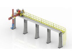
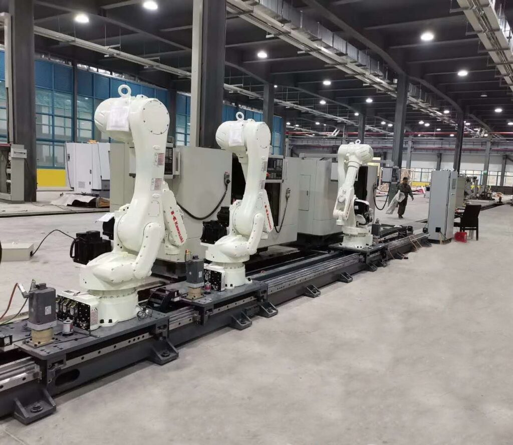
 Robot Linear track
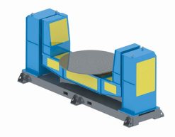 Robot welding Positioner
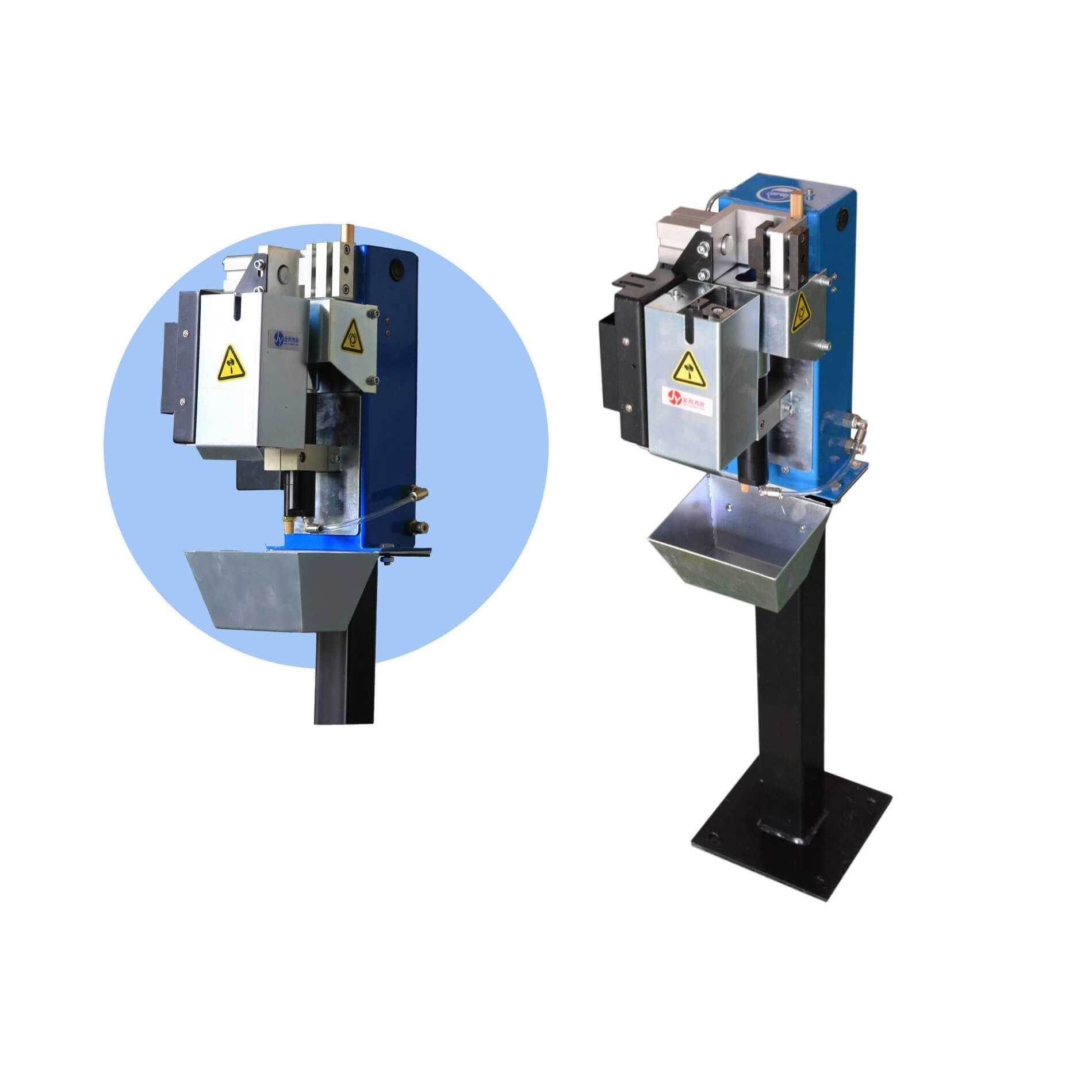 Robot Torch cleaning station
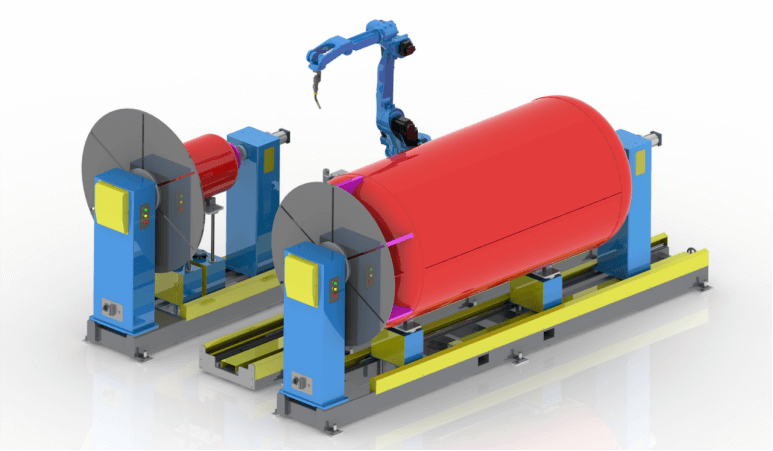 Welding Robot Workstations & Automation Solutions
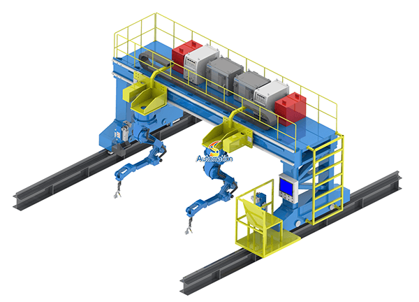 Robot Gantry System
The robot was calibrated. The welds still missed.
A welding integrator called us about a cell that had been running for three weeks. The robot was fine. The track was fine. The positioner was fine. Every axis had been calibrated during commissioning, the numbers were written down, and the handover sheet said so. And yet the welds kept landing a few millimetres off the seam — not always, and not in the same direction, which was the part that made everyone suspicious of the robot.
It was not the robot. It was the calibration — or rather, the assumption that calibration is something you do once, at commissioning, and then forget about. In our experience, most external axis calibration failures have nothing to do with the calibration procedure itself. The procedure works. What fails is everything around it: a mastering value recorded against the wrong mark, a workpiece that moved between teaching and production, a base frame that was defined before the track was levelled, a gear ratio typed in from the wrong datasheet. The calibration was done correctly, against the wrong reality.
This article is about the seven ways external axis calibration actually fails in the field, how to recognise each one, and what to do about it. If you are commissioning a 7th axis or a welding positioner, or if a cell that used to weld perfectly has started drifting, this is the checklist we work through first.
First, what calibration actually is — and what it is not
It helps to be precise about the word, because three different things get called “calibration” on the shop floor, and they fail in different ways.
Mastering is telling the controller where the axis physically is. On a robot this is the zero position of each joint; on an external axis it is the reference position of the track carriage or the positioner table, usually set against a mechanical mark or a reference switch. If the mastering is wrong, every move the axis makes is offset by the same amount, in the same direction, every time.
Base frame definition is telling the controller where the axis sits in the world. A 7th axis is not a robot joint; it is a separate piece of equipment that the robot controller has to know about. The controller needs the track’s position and orientation relative to the robot’s base frame — its X, Y and Z offsets and its rotation. If that frame is wrong, the robot’s calculated positions drift as the carriage moves along the track, and the error grows with the distance travelled.
Kinematic parameters are the numbers that describe how the axis actually moves: the gear ratio, the rack pitch or ball screw lead, the encoder resolution, the direction of rotation. If any of these is wrong, the axis moves a different distance than the controller thinks it moved, and the error grows with every metre of travel.
All three have to be right. A perfect mastering with a wrong gear ratio still misses. A perfect gear ratio with a base frame defined before the track was levelled still misses. And the painful part is that each failure looks different on the shop floor — which is exactly why it is worth knowing them apart.
1. The mastering mark was wrong — or it moved
This is the most common failure we see, and the simplest. Mastering is usually done against a scribed line, a dowel hole, or a reference switch, and the whole calibration depends on that mark being exactly where the drawing says it is.
In practice, marks get scribed by hand during installation, sometimes in a hurry, sometimes on a track that was not yet levelled. We have seen mastering marks that were a full two millimetres off the true zero because the track had been levelled after the mark was made, not before. The calibration was done carefully, against a mark that was wrong, and every weld after that carried the same two-millimetre offset.
It also happens the other way round: the mark is right, but someone re-masters the axis later — after a motor change, a battery replacement, a controller swap — and uses a different reference point, or reads the mark from a different angle, or works from a photograph instead of the mark itself. The new mastering is a millimetre or two away from the old one, and suddenly every taught point is off by that amount.
The fix is unglamorous. Master against a fixed, machined reference, not a hand-scribed line if you can avoid it. Record the mastering method and the reference used in the commissioning file — which mark, which switch, which direction the axis was approached from — so that the next person to re-master the axis does it the same way. And always re-verify mastering with a physical check: drive the axis to its reference position and measure it, don’t just trust the number on the screen.
2. The base frame was defined before the track was finished
A 7th axis base frame is normally defined by teaching three points, or by measuring the track with a laser tracker, and the result is a set of offsets that the robot controller uses for every coordinated move. The frame is only as good as the track was when it was measured.
The classic mistake is to define the base frame while the track is still being installed — before the final levelling, before the grout has cured, before the anchor bolts are torqued to their final value. The track moves a fraction of a millimetre when the grout sets and the bolts are tightened. That is not much, and it is exactly the amount that shows up as a calibration error afterwards. The frame says the track is in one place; the track is in another, a millimetre away, and the error is worst at the far end of the travel.
We covered the installation side of this in our article on robot track installation mistakes: level and torque the track first, then measure, then define the frame. The order matters, and it cannot be reversed afterwards. If the base frame was defined early, it has to be re-defined after the installation is complete. There is no shortcut, and re-teaching a few points is far cheaper than chasing a phantom accuracy problem for weeks.
There is a related version of the same failure on positioners. A positioner’s base frame is defined relative to the robot, and if the positioner is moved — even slightly, even by a forklift bump during a cell rearrangement — the frame is wrong. After any move, however small, re-check the frame before you trust the programs.
3. The wrong gear ratio, or the wrong sign
This one is embarrassing, and it happens more often than anyone admits. The external axis needs a gear ratio, a rack pitch or screw lead, and an encoder count per revolution, and those numbers come from the drive datasheet. On a rack-and-pinion track the critical number is the pinion pitch diameter; on a ball screw track it is the screw lead. Get one of them wrong and the axis moves a different distance than the controller commands.
The failure mode is distinctive: the error grows with distance. A program taught near the home position looks fine, and the same program run three metres down the track is off by several millimetres. If the error is proportional to how far the axis has moved, the kinematic parameters are the first thing to check.
The other version is the sign: the axis is configured to move in the opposite direction to the one the controller expects. This is usually caught immediately, because the robot drives the wrong way, but a subtle version exists where the axis direction is right and the encoder direction is reversed, which shows up as a position that is correct at the reference point and wrong everywhere else.
The fix is to check the numbers against the actual hardware, not against the quotation. Gearboxes get substituted, pinions get changed, a different motor is fitted during a repair — and the datasheet in the file describes the axis as it was ordered, not as it was built. Measure the real travel: command the axis to move a known distance and measure it with a dial indicator or a laser. If the measured distance does not match the commanded distance, the parameters are wrong, and no amount of re-mastering will fix it.
4. The workpiece moved — and nobody told the robot
This is not a calibration failure in the strict sense, which is exactly why it gets misdiagnosed as one. The calibration is fine. The workpiece is not where the program thinks it is.
It happens in two ways. The first is the obvious one: the fixture or the positioner table was adjusted, the workpiece is loaded differently, a new batch of parts has a different tolerance, and the taught points no longer match the real seam. The robot is doing exactly what it was told; what it was told is no longer true.
The second is subtler, and it is specific to welding. Heat distorts the workpiece. A long beam welded on a positioner grows and bends as it heats up, and by the third pass the seam has moved a millimetre or two from where it was when the program was taught cold. The first weld is perfect; the last one misses. The calibration looks guilty, but the workpiece moved.
The fix for the first is process discipline: any change to the fixture, the loading method, or the part itself means the reference points get re-checked before production restarts. The fix for the second is to teach with distortion in mind — weld in a sequence that balances the heat, use the positioner to present the seam in the same orientation for each pass, and where the application allows it, use seam tracking or a touch-sensing routine to find the real seam before each weld rather than trusting the taught position.
5. Backlash was calibrated out — then it came back
Every rack-and-pinion drive and every gearbox has backlash: a small amount of play that shows up when the direction of motion reverses. During commissioning, backlash is measured and compensated in the controller, usually as a single number. That works — until the backlash changes.
Backlash grows as gears wear, and it changes with load and temperature. A compensation value set on a new, cold track in the factory will not be exactly right on a worn track running at production temperature in a hot shop. And if the backlash is compensated in only one direction of travel, programs that approach a point from the opposite direction will be off by the full backlash amount.
The symptom is a familiar one: the weld is right when the robot approaches from one side, and wrong when it approaches from the other. Or the first weld of the day is fine and the error creeps in as the cell warms up. Both point at backlash, not at the mastering.
The fix is to measure backlash in both directions, under load, at working temperature — not just on the bench. And to treat backlash compensation as a maintenance item, re-checked on a schedule, not as a number set once at commissioning. We wrote about the longer-term side of this in our article on why a robot track loses accuracy after six months; backlash growth is one of the mechanisms behind it.
6. The encoder lost its position — and nobody noticed
Absolute encoders remember their position when the power is off. Incremental encoders do not, and they rely on a battery-backed reference or a homing routine after every power cycle. That distinction matters more than it sounds.
If an incremental encoder’s battery dies, or a cable is disturbed during maintenance, the axis loses its reference. The controller may not flag it clearly — the axis still moves, the program still runs, but the whole coordinate system has shifted by whatever distance the axis moved while the reference was lost. The cell looks calibrated and is not.
A related failure is the encoder coupling. A loose coupling between the motor shaft and the encoder slips a fraction of a degree at a time, under load, and the controller never sees it because the encoder is measuring the motor, not the load. The axis reports that it is in position; the carriage is a millimetre away. This is a mechanical failure wearing a calibration costume.
The fix is partly procedural and partly mechanical. After any power loss, battery change, cable work or motor work, re-home the axis and verify the reference before running production. Check encoder couplings during scheduled maintenance — a coupling that can be turned by hand is a coupling that is about to cause a calibration problem. And where the application allows it, prefer absolute encoders on external axes, so that a power cycle cannot silently erase the reference.
7. The calibration was done — but never verified under load
This is the quietest failure of all, because everything looks right on paper. The mastering is correct, the base frame is correct, the parameters are correct. The axis was calibrated unloaded, on a cold track, with no workpiece on the positioner. Then production starts, and the robot, the fixture and a two-tonne workpiece are added to the equation.
Under load, a track deflects. A positioner table sags a fraction of a millimetre. A long cantilever carriage twists slightly when the robot extends to full reach. None of this shows up in an unloaded calibration, and all of it shows up in the weld.
The fix is to verify calibration the way the cell will actually run: with the robot mounted, the positioner loaded with a representative workpiece, and the track at working temperature. The factory acceptance test is the place for this. During FAT, the robot should be driven to both ends of the track, with the positioner loaded, and asked to reach a target at each station — the same test we recommend in our article on robot track travel versus effective travel. If the calibration only holds when the cell is empty, it does not hold.
How we work through a calibration failure
When a customer calls us about a cell that has started missing, we do not start by re-running the calibration. We start by asking what the error looks like, because the pattern tells you where to look:
- The same offset, everywhere, in the same direction: mastering. Re-master against the original reference and verify it physically.
- The error grows with distance along the track: kinematic parameters, or a base frame defined before the track was finished. Check the gear ratio and the measured travel first.
- The error is worst at the far end of the track: base frame, or track deflection under load. Re-measure the frame and verify under load.
- The error depends on which direction the axis approached from: backlash. Measure it in both directions, under load, at working temperature.
- The error appears after a power cycle, a battery change, or maintenance: encoder reference lost. Re-home and verify before production.
- The error appears only on later weld passes, or only on some parts: the workpiece moved. Check the fixture, the loading, and the welding sequence.
- The error appears gradually over weeks or months: wear — backlash growth, foundation movement, or a loosening coupling. Treat it as a maintenance signal, not a calibration event.
That list is worth keeping near the cell. It turns a day of guessing into an hour of checking.
Checklist: before you sign off a calibration
- Mastering is done against a fixed, machined reference, and the method is written in the commissioning file.
- The base frame was defined after final levelling, grouting and bolt torquing — not before.
- Gear ratio, rack pitch or screw lead, and encoder counts were checked against the hardware as built, not the quotation.
- Measured travel matches commanded travel over the full stroke, in both directions.
- Backlash is measured in both directions, under load, at working temperature.
- The reference position is verified physically after every power cycle, battery change, or motor or cable work.
- The calibration is verified with the robot mounted and the positioner loaded with a representative workpiece.
- The FAT includes driving the robot to both ends of the track and reaching a target at each station.
- Fixture, loading method, and workpiece tolerances are recorded, and any change triggers a re-check.
- The mastering method, base frame values, and backlash compensation are all written down in one place, so the next person does not have to guess.
FAQ
How often should an external axis be re-calibrated?
There is no single interval. Re-calibrate after any event that can move the reference: a motor or encoder change, a battery replacement, a controller swap, a track or positioner move, or a foundation repair. Apart from that, verify the calibration on a schedule — monthly for a high-duty welding cell is a reasonable starting point — and re-calibrate when the verification shows a drift, not on a fixed calendar date.
Can I calibrate a 7th axis myself, or does it need the robot manufacturer?
The mechanical part — mastering, measuring travel, checking backlash — can be done by any competent integrator with the right instruments. The controller-side part depends on the robot brand: ABB, FANUC, KUKA and Yaskawa each have their own external-axis setup and coordinated-motion configuration, and the calibration has to be entered in the form that controller expects. If you are unsure, have the robot brand’s procedure open in front of you while you work, or ask the axis supplier to walk through it with you.
Why does the error get worse the further the robot travels along the track?
Because the errors that grow with distance are the kinematic ones: a wrong gear ratio, a wrong rack pitch, or a base frame that is slightly rotated relative to the track. A mastering error is constant everywhere. An error that grows with distance is telling you the controller’s model of the axis does not match the axis itself.
My positioner was calibrated, but the welds are off only when the table rotates. What is that?
That usually points at the positioner’s own frame — the rotation axis is not where the controller thinks it is, or the workpiece centre of gravity is offset from the rotation axis and the table sags under load. Check the rotation-axis alignment and verify the calibration with the actual workpiece mounted, not empty.
Is a laser tracker necessary for external axis calibration?
Not always. A dial indicator, a straightedge and a careful mastering routine will catch most of the failures in this article. A laser tracker becomes worth it on long tracks — ten metres and up — where a small angular error in the base frame turns into a large positional error at the far end, and where you need to prove the frame rather than assume it.
Calibration is a habit, not an event
The cells that hold their accuracy are not the ones that were calibrated most carefully at commissioning. They are the ones where calibration is treated as a habit: verified after every intervention, checked on a schedule, and written down so the next person starts from the same numbers instead of from scratch. The hardware in a 7th axis or a welding positioner is, in our experience, rarely the problem. The problem is almost always the chain of assumptions between the drawing and the shop floor — and that chain is exactly what a good calibration routine is for.
If your cell has started missing welds, or if you are commissioning a new track or positioner and want the calibration done properly from the start, send us your robot model, the axis type, and a description of what the error looks like — whether it is constant, whether it grows with distance, and whether it depends on the direction of approach. That pattern tells us where to look, and it will usually tell you too. You can reach our engineering team through the contact page, or browse our robot linear track range and our welding positioner range to see the equipment we build.
By WRS Robotics Engineering Team