
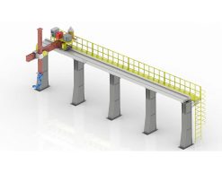
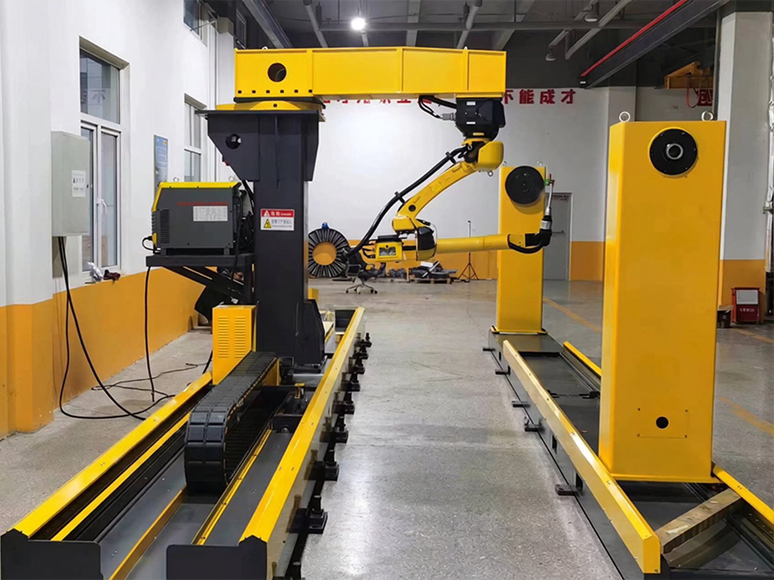
 Robot Linear track
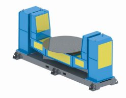 Robot welding Positioner
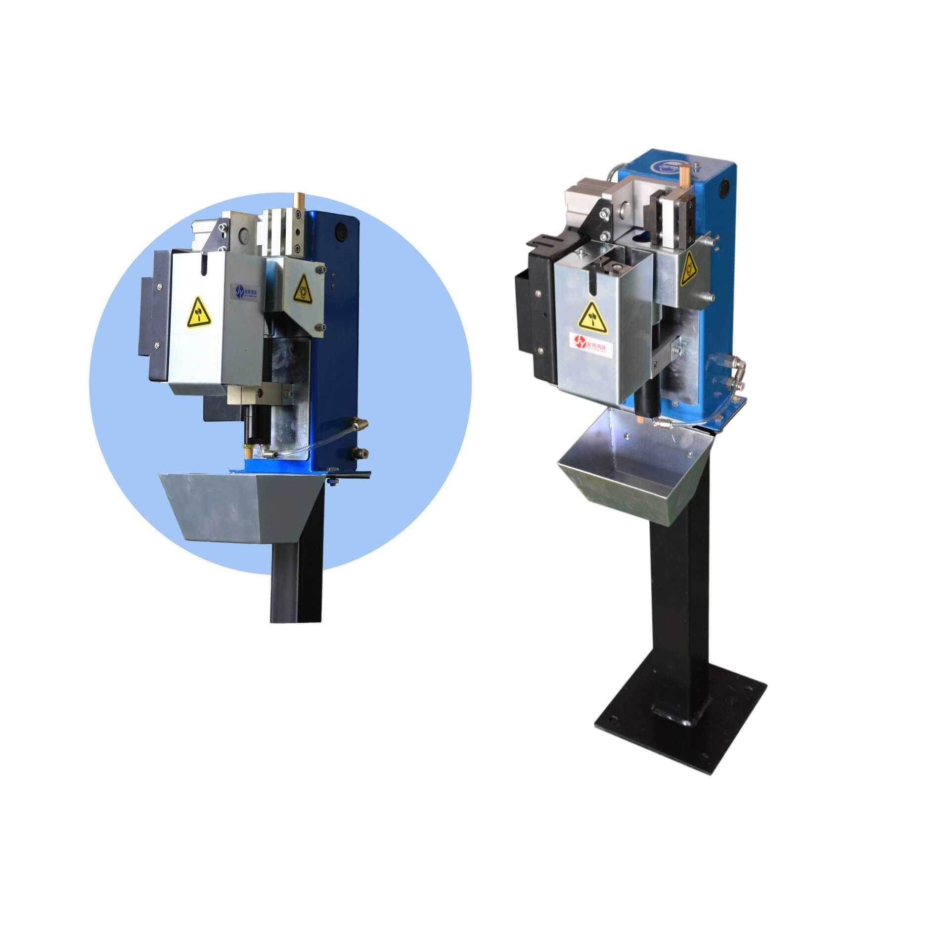 Robot Torch cleaning station
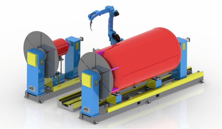 Welding Robot Workstations & Automation Solutions
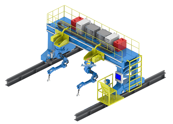 Robot Gantry System
The weld was perfect on one side. On the other side, it was a mess.
A welding integrator called us about a cell we had supplied the positioner for. The robot was welding a long structural beam on a two-axis headstock-tailstock positioner, and the welds kept coming out uneven. On the near side of the beam the bead was clean and consistent. On the far side it was lumpy, with undercut in places and lack of fusion in others. The welding parameters had not changed. The robot program had not changed. The only thing that changed was where the positioner was pointing.
We went to site and watched the cell run. The problem was obvious once you saw it. The robot was welding while the positioner was still moving. Not much — just a few degrees — but enough that the torch angle was drifting away from the seam while the arc was on. The positioner had been programmed to rotate to the next weld position, and the robot had been told to start welding as soon as the positioner reported “in position”. But “in position” was a digital signal that fired a fraction of a second before the positioner had actually settled. The robot was chasing a moving workpiece.
That is what synchronization is really about. It is not a setting you turn on. It is the question of whether the robot and the positioner actually know where each other are, at every moment of the weld — or whether they are just taking turns and hoping the timing works out. Get it right, and the torch stays at the right angle to the seam for the whole weld, the positioner turns the workpiece into the flat position exactly when the robot needs it, and the cell runs faster because nobody is waiting for anyone else. Get it wrong, and you get uneven welds, rework, and a cell that looks automated but still needs an operator watching it.
This article explains how synchronization actually works, brand by brand — ABB, FANUC, KUKA and Yaskawa — because the four of them do the same job in four different ways, and the differences matter when you are specifying a cell. It also covers the simpler setups where full synchronization is not needed, the commissioning steps that decide whether it works on day one, and the mistakes we see most often.

What “synchronized” actually means — three levels, not one
People use the word synchronization to mean different things, and that causes a lot of confusion in project meetings. In practice there are three levels, and each one is a different engineering decision.
Level 1: Index and weld. The positioner moves the workpiece to a position, stops, and signals the robot. The robot welds. The positioner moves to the next position. The robot and the positioner never move at the same time. This is the simplest setup, and for a lot of work it is all you need — short welds on a workpiece that can be presented flat, one seam at a time. The positioner can be driven by its own servo and PLC, or by the robot controller, but the two are not coordinated. They just take turns. The cost is cycle time: every index is dead time, and every weld has to be short enough that the workpiece does not need to move while the arc is on.
Level 2: Coordinated motion. The positioner is configured as an external axis of the robot — a 7th, 8th or 9th axis — and the robot controller drives it. The robot and the positioner move together in the same motion instruction, so the workpiece rotates while the robot welds, and the torch angle stays constant relative to the seam. This is what most people mean when they say “synchronized”. It is the standard approach for long seams on cylindrical or structural workpieces, where the weld has to stay in the flat or horizontal position for its full length. It needs the robot controller to have the external-axis option and the positioner servo to be driven by the robot controller’s drive system.
Level 3: Continuous coordinated motion with torch angle control. This is level 2 with the programming done properly: the positioner speed is matched to the welding speed so the torch stays at the same angle and the same travel speed relative to the seam for the entire weld, including around curves and changes of direction. It is what you need for circumferential welds on pipes and pressure vessels, and for long seams where the workpiece geometry changes along the weld. It is not a different piece of hardware — it is the same external-axis setup, programmed with the weld path defined relative to the workpiece, so the controller works out the positioner motion for you.
Which level you need depends on the weld, not on the budget. If the workpiece can be welded flat in short runs, level 1 is fine and cheaper. If the seam is long, curved, or needs to stay in the flat position while the arc is running, you need level 2 or 3. The mistake we see most often is buying a servo positioner and a robot controller with the coordinated-motion option, and then programming it as level 1 anyway — paying for synchronization and never using it. The other mistake is the opposite: buying a PLC-driven positioner for a job that needs continuous coordinated motion, and then discovering during commissioning that the weld quality is not good enough and there is no way to fix it in software.
The basic idea is the same on every brand
Before the brand differences, it helps to understand what is common. On all four brands, a synchronized positioner is treated as an extra axis of the robot system. The robot controller drives the positioner’s servo motor through its own drive system, the same way it drives the robot’s six axes. The positioner’s axis is given a name — usually the 7th axis, or the 8th and 9th for a two-axis positioner — and its position is part of the robot’s motion data. When the robot program says “move to this point”, the point includes where the positioner should be, and the controller moves both together, at speeds it calculates so they arrive at the same time.
That is the whole trick. Once the positioner is an axis of the robot, the controller’s path planner treats the robot and the positioner as one machine. The torch stays at the programmed angle to the workpiece because the workpiece frame moves with the positioner, and the controller knows exactly where the workpiece is at every point in the program.
Getting there requires four things, on every brand: the right software option in the robot controller, the right servo motor and drive for the positioner, the mechanical coupling between the motor and the positioner axis (gearbox ratio, encoder), and the calibration that tells the controller where the positioner axis actually is in space. The brands differ in what they call these things and how you configure them, but the four items are the same. If any one of them is wrong, the cell will not synchronize properly, and the symptom is usually the same: the weld looks fine at the start of the seam and drifts off as the positioner turns.
ABB: the positioner as a mechanical unit
ABB treats the positioner as a “mechanical unit” added to the robot system. In RobotStudio, the offline programming software, you configure the positioner as an external axis — a 7th axis for a single-axis positioner, or 7th and 8th axes for a two-axis headstock-tailstock or L-type unit. The mechanical unit definition includes the gearbox ratio, the motor type, and the axis limits, and RobotStudio uses it to simulate the whole cell, positioner included, before anything is built.
In the RAPID program, the positioner’s position is part of every motion target. A robtarget carries the robot’s six joint values plus the external axis values, so when you program a weld, you program where the positioner should be at each point along the seam, and the controller moves the robot and the positioner together in the same MoveL or MoveJ instruction. That is coordinated motion in ABB terms: one instruction, two mechanisms, one path.
Two things about ABB are worth knowing before you specify a cell. First, ABB’s coordinated motion works best when the positioner is defined with its own work object that moves with the positioner axis — the weld path is programmed relative to the workpiece, and the controller works out the positioner rotation needed to keep the torch angle constant. If the weld is programmed in the robot’s base frame instead, the programmer has to calculate the positioner motion by hand, and that is where errors creep in. Second, ABB controllers support MultiMove, which lets one controller drive two robots and external axes together. If your cell has two robots welding on one positioner, MultiMove is how they stay synchronized with each other as well as with the positioner.
The practical point for integrators: ABB’s offline simulation is genuinely useful here. You can check the full coordinated motion in RobotStudio — torch angles, positioner speeds, reach limits — before the cell is built, and the program that runs in simulation is the program that runs on the real controller. That is worth using, because the mistakes that are cheap to fix in simulation are expensive to fix on site.
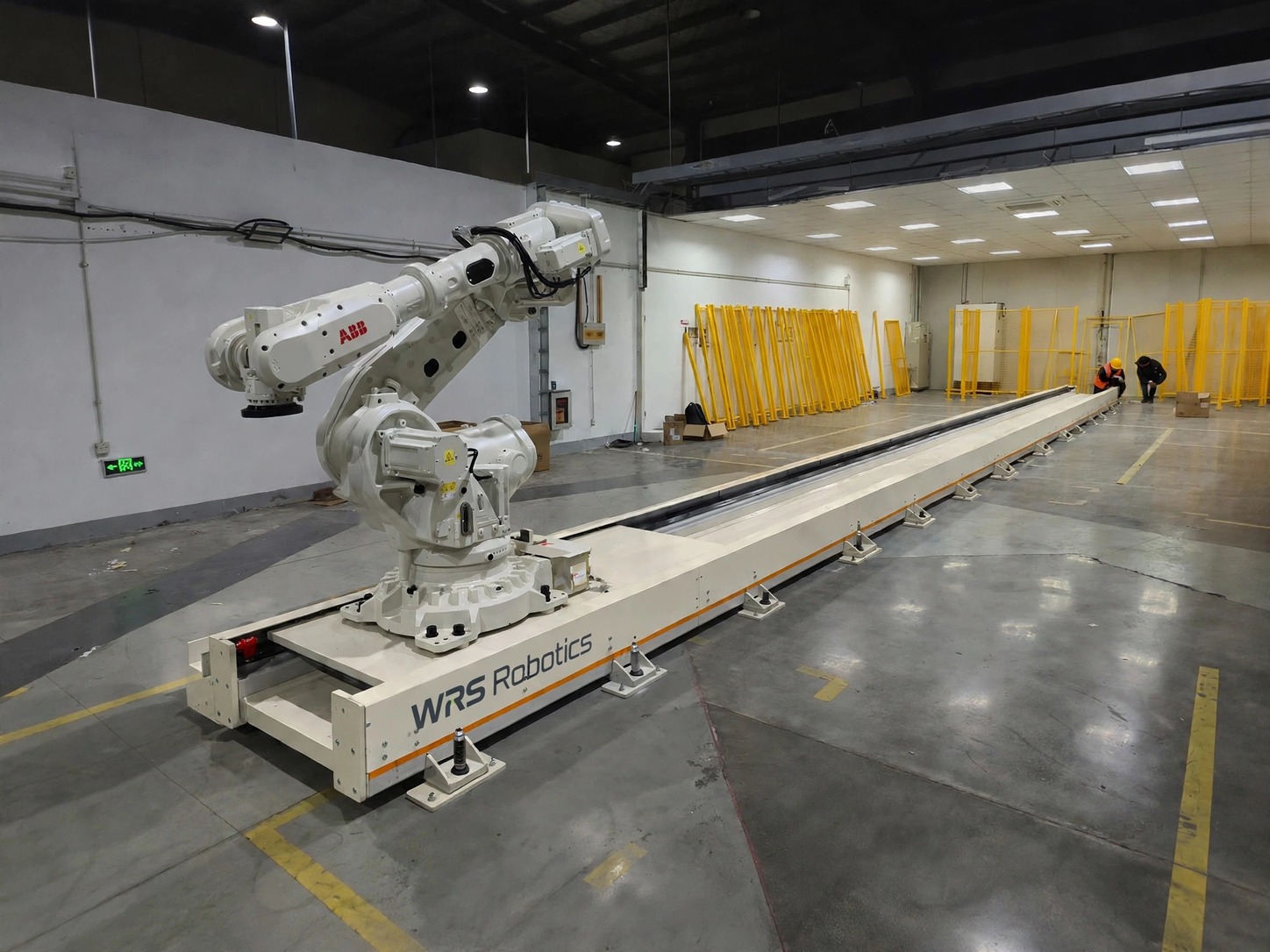
FANUC: the positioner as an extended axis
FANUC calls the positioner an “extended axis” or an additional motion group. On the R-30iB controller, the positioner axes are configured as a second motion group — group 2 — alongside the robot’s group 1. A single-axis positioner is one extended axis; a two-axis positioner is two. The servo amplifier for the positioner sits in the same controller cabinet as the robot’s, and the axes are driven by the same motion planner.
FANUC’s coordinated motion option lets the robot and the positioner move together in the same program. In the teach pendant program, the positioner axis values are part of the position data, and a coordinated motion instruction moves the robot and the positioner at the same time, keeping the torch angle relative to the workpiece. FANUC also offers a simpler mode, where the positioner is driven as an independent group and the program switches between moving the robot and moving the positioner — that is level 1, index and weld, and it is fine for cells that do not need continuous motion.
One thing FANUC users run into is the safety setup. FANUC’s DCS (Dual Check Safety) defines safe zones and speed limits, and the positioner axes need to be included in the DCS configuration — their range of motion, their speed limits, and the zones they are allowed to enter. If the positioner is added to the cell after the DCS setup is done, and nobody updates the safety configuration, the controller will fault the first time the positioner moves outside the zone it was originally given. It is not a synchronization problem, but it looks like one, and it stops the cell just as effectively.
The other thing to know is that FANUC’s coordinated motion is a software option, not a standard feature on every controller. It has to be ordered with the robot, or added later with a software key. If you are buying a FANUC robot for a cell with a synchronized positioner, check that the coordinated motion option is on the order. Adding it after delivery costs time and money, and we have seen projects delayed by weeks because nobody checked.
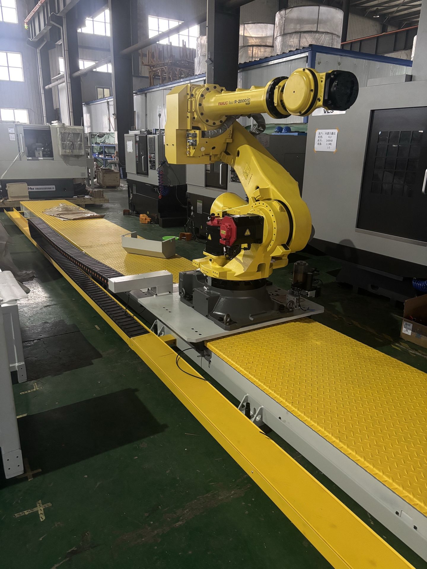
KUKA: external axes in WorkVisual
KUKA configures the positioner as an external axis — E1 to E6 — in WorkVisual, the engineering software for the KRC4 controller. The positioner is set up as an “external kinematic system”, with its own axis data, gearbox ratio, and limits, and the KRC4 drives it through an additional servo drive in the controller cabinet. A two-axis positioner uses E1 and E2.
In the KUKA program, the positioner’s axis values are part of the motion data, in the same way as on ABB and FANUC. A PTP or LIN instruction that includes the external axis values moves the robot and the positioner together, and the controller coordinates their speeds so they arrive together. KUKA also lets you move the external axis on its own — an asynchronous motion — which is useful for loading and unloading, where the positioner needs to turn to the operator while the robot waits.
KUKA’s strength in this area is the offline setup. WorkVisual lets you configure the whole kinematic chain — robot, positioner, and any linear track — as one system, and check the motion in simulation before commissioning. That matters, because the most common KUKA synchronization problem we see is a wrong gearbox ratio in the external axis configuration. The positioner turns, but by the wrong amount, and the error grows with every degree of rotation. It is a configuration mistake, not a mechanical one, and it is much easier to catch in WorkVisual than on the shop floor with a dial gauge.
KUKA also has KUKA.SafeOperation, the safety option that monitors axis positions and speeds. Like FANUC’s DCS, it needs to know about the positioner axes. If the safe monitoring is set up for the robot alone and the positioner is added later, the safety system will not cover it, and the cell will not pass a safety audit. Include the positioner in the safety configuration from the start.
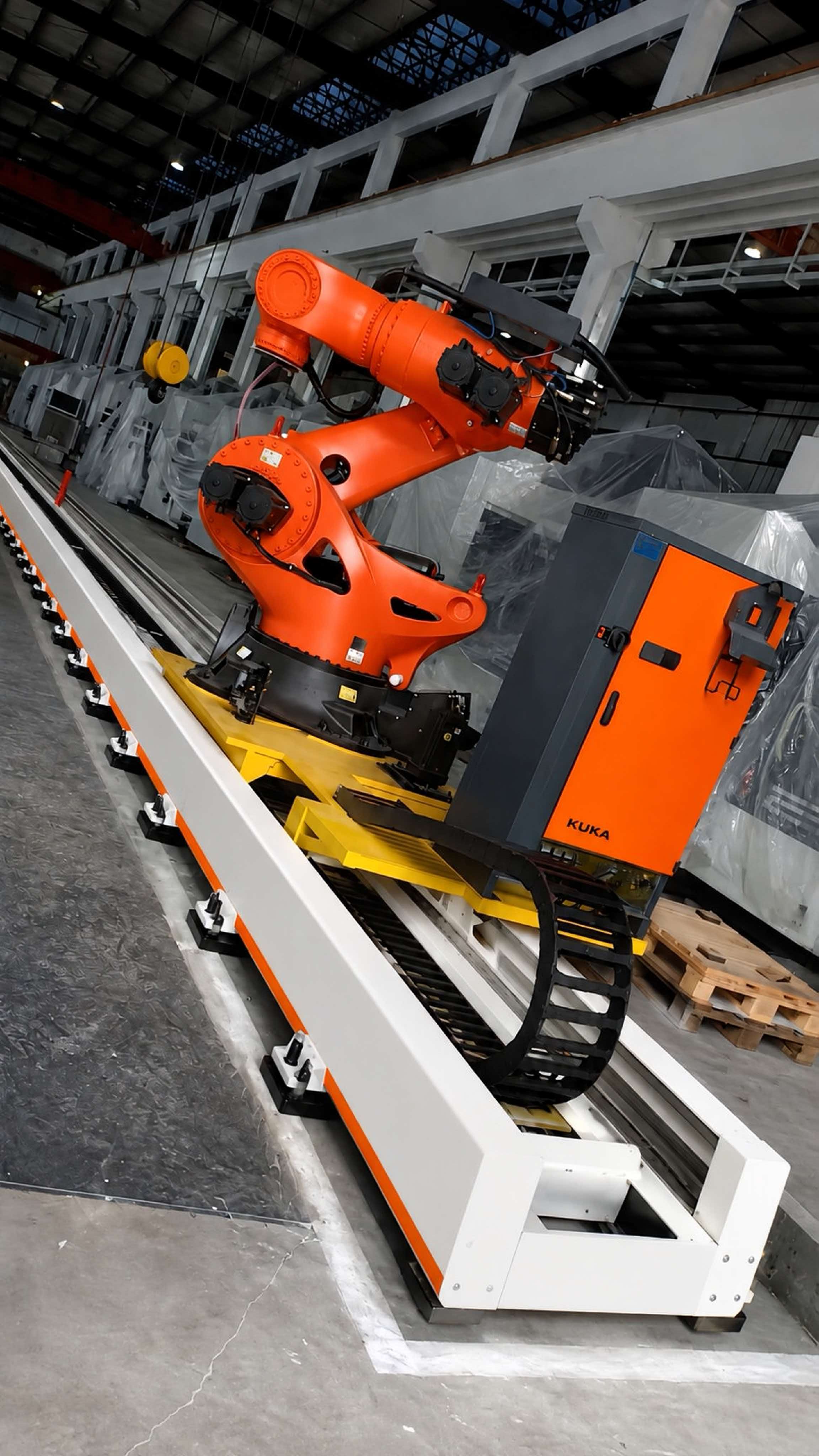
Yaskawa: coordinated motion on the YRC1000
Yaskawa’s approach is closest to FANUC’s. On the YRC1000 (and the older DX200), the positioner is configured as an external axis — an additional axis driven by the robot controller — and Yaskawa’s coordinated motion function moves the robot and the positioner together. In the job program, the positioner axis values are part of the motion data, and a MOVL or MOVJ instruction that includes them moves both mechanisms in a coordinated way.
Yaskawa’s coordinated motion is particularly well developed for welding, because a large share of Yaskawa’s robot business is arc welding. The controller supports “coordinated motion” where the welding speed is defined relative to the workpiece, and the positioner rotation speed is calculated automatically so the torch travel speed along the seam stays constant even as the workpiece turns. For circumferential welds on pipes and pressure vessels, that is exactly what you need: the torch moves at a steady speed around the pipe, and the weld bead stays consistent for the full circle.
MotoSim, Yaskawa’s offline programming and simulation software, is the place to set all of this up. Like RobotStudio and WorkVisual, it lets you build the whole cell — robot, positioner, workpiece — and check the coordinated motion before the hardware arrives. Yaskawa also publishes detailed application notes for positioner integration, which are worth reading before you start, because the parameter names and the setup sequence are specific to Yaskawa and easy to get wrong if you are coming from another brand.
One practical note: Yaskawa controllers are often supplied with the positioner servo amplifier as a separate unit, and the cabling between the controller and the positioner motor needs to be the right length and properly routed. A positioner that rotates 360 degrees needs its cables managed so they do not wind up or snag, and the servo cable length affects the drive tuning. These are installation details, but they decide whether the coordinated motion is smooth or whether the positioner hesitates and jerks at the start of every move.
How the four brands compare
| ABB | FANUC | KUKA | Yaskawa | |
|---|---|---|---|---|
| Positioner in the controller | Mechanical unit (external axis) | Extended axis, motion group 2 | External axis E1–E6 | External axis (additional axis) |
| Configuration software | RobotStudio | Teach pendant / iPendant | WorkVisual | Pendant / MotoSim |
| Coordinated motion | Same MoveL/MoveJ instruction, robtarget carries external axis values | Coordinated motion option, positioner values in position data | PTP/LIN with external axis values in motion data | Coordinated motion function, MOVL/MOVJ with positioner values |
| Workpiece frame | Work object on the positioner axis | User frame on the positioner | Base frame on the external kinematic system | User coordinate on the positioner axis |
| Safety integration | SafeMove | DCS (Dual Check Safety) | KUKA.SafeOperation | Functional safety on YRC1000 |
| Multi-robot on one positioner | MultiMove | Multi-arm / coordinated control option | Two robots via one controller option | Coordinated control option |
The table makes the brands look more different than they are. In practice, the engineering is the same on all four: the positioner is an axis, the controller drives it, and the program carries its position. What changes is the configuration software, the option names, and the details of the safety setup. An integrator who has done this on one brand can do it on another — but only if they read that brand’s manual instead of assuming it works the same way.
When a PLC-driven positioner is the right answer
Not every cell needs the robot controller to drive the positioner. A positioner with its own servo drive and a PLC is simpler, cheaper, and easier to maintain — and for a lot of cells it is the right choice. The PLC moves the positioner to a programmed position, the robot waits for the “in position” signal, welds, and then signals the PLC to index to the next position. There is no coordinated motion, but there is also no software option to buy, no external-axis configuration to get wrong, and no dependency between the robot brand and the positioner supplier.
This works well when the welds are short, the workpiece can be presented flat for each weld, and the cycle time penalty of indexing is acceptable. It works badly when the seam is long or curved, when the weld has to stay in the flat position while the arc is running, or when the workpiece is heavy enough that the indexing time dominates the cycle. It also works badly when the cell is later upgraded — a PLC-driven positioner cannot be turned into a coordinated-motion positioner by a software change, because the servo drive and the motor are not connected to the robot controller. If there is any chance the cell will need coordinated motion in the future, it is worth fitting the robot-controller-driven servo from the start, even if the first program only uses index and weld.
The decision, in short: buy the synchronization capability for the welds you will have in two years, not just the welds you have today.

Commissioning: the steps that decide whether it works
Synchronization is mostly decided during commissioning, not during programming. The steps below are the ones that matter, and they are the same whichever brand you are using.
1. Mechanical alignment first. Before any software configuration, the positioner axis has to be mechanically aligned — its rotation axis square to the robot, its centreline where the drawings say it is, and its bearings free of play. If the mechanical alignment is off, no amount of software calibration will fix it, because the error changes as the positioner rotates. We covered the mechanical side of alignment in our guide to 7 common robot linear track installation mistakes — the same discipline applies to positioners.
2. Gearbox ratio and encoder setup. The controller needs to know exactly how many degrees the positioner turns for each turn of the servo motor. That is the gearbox ratio, and it has to be entered correctly in the external-axis configuration. A wrong ratio is the single most common commissioning mistake, and the symptom is distinctive: the positioner moves, but the error grows with the angle. A 1-degree error at 10 degrees becomes a 10-degree error at 100 degrees. Check it by commanding a known rotation — 90 degrees, for example — and measuring the actual rotation with a dial gauge or a level before you weld anything.
3. Mastering and calibration. The positioner’s zero position has to be defined and mastered, the same way the robot’s axes are mastered. If the positioner is re-mastered after a motor replacement or a controller backup restore, the zero can shift, and every weld after that will be off by the same amount. Keep a record of the mastering values, and re-check them after any maintenance that touches the servo motor, the encoder, or the controller.
4. Workpiece frame definition. The weld path is programmed relative to the workpiece, and the workpiece sits on the positioner. The controller needs a coordinate frame that moves with the positioner axis, so that when the positioner turns 30 degrees, the controller knows the workpiece has turned 30 degrees. On ABB that is a work object on the mechanical unit; on FANUC and Yaskawa it is a user frame tied to the positioner axis; on KUKA it is a base frame on the external kinematic system. The name is different; the job is the same. If this frame is defined in the robot’s base coordinates instead, the weld path will be correct at one positioner angle and wrong at every other.
5. Speed and acceleration matching. The positioner has to be fast enough to keep up with the robot, and slow enough not to shake the workpiece. A heavy workpiece on a two-axis positioner has a lot of inertia, and if the positioner accelerates too hard, the workpiece vibrates and the weld pool moves. Set the positioner acceleration conservatively at first, verify the weld quality, and only then increase it. The cycle time you lose to a gentle acceleration is far less than the time you lose to rework.
6. Low-speed dry run. Before the first arc is struck, run the full coordinated program at low speed with the torch off, and watch the torch-to-workpiece angle at every point in the weld. If the angle drifts, or the positioner hesitates, or the robot reaches a limit, you will see it in a dry run. You will not see it in a simulation, because the simulation assumes the configuration is correct — and the configuration is exactly what is being tested.
7. Safety verification. Include the positioner axes in the safety configuration — zones, speed limits, and safe monitoring — and test it. A positioner that can rotate into the operator loading area while the robot is running is a safety failure, not a programming detail.
The synchronization mistakes we see most often
1. Programming coordinated motion in the robot’s base frame. The weld path has to be relative to the workpiece, which moves with the positioner. Program it in the base frame and the path is only right at one angle.
2. A wrong gearbox ratio. The positioner turns by the wrong amount, and the error grows with the rotation. Always verify with a measured 90-degree move before welding.
3. Forgetting to master the external axis after maintenance. A motor or encoder change shifts the zero. Every weld after that is off by the same amount, and the cause is not obvious because the robot itself is fine.
4. Using the “in position” signal as the weld start. A digital signal can fire before the positioner has settled. Wait for the axis to settle — or better, use coordinated motion, where there is no handover at all.
5. Buying a PLC-driven positioner for a job that needs coordinated motion. The weld quality problem only appears during commissioning, when it is too late to change the drive system cheaply.
6. Not ordering the coordinated-motion software option. On FANUC and others it is an option, not standard. Check the order before the robot ships.
7. Leaving the positioner out of the safety configuration. DCS, SafeMove, SafeOperation and Yaskawa functional safety all need to know about the positioner axes. A cell that faults every time the positioner moves is not synchronized — it is stopped.
8. Skipping the dry run. The first time the full coordinated program runs should be at low speed with the torch off. Finding a problem with the arc on means scrapping a workpiece.
Synchronization checklist
Use this before ordering, and again at commissioning.
- Weld type confirmed: index-and-weld or continuous coordinated motion — decided from the weld, not the budget
- Robot brand and controller model confirmed, with the coordinated-motion / external-axis software option on the order
- Positioner servo motor and drive matched to the robot controller (same brand drive system, correct amplifier size)
- Gearbox ratio, encoder type and axis limits documented and entered in the external-axis configuration
- Workpiece frame defined on the positioner axis, not in the robot base frame
- Positioner included in the safety configuration (DCS / SafeMove / SafeOperation / functional safety)
- Cable and dress-pack routing checked for the full rotation range, with no wind-up or snagging
- Gearbox ratio verified with a measured 90-degree move before the first weld
- External axis mastered, mastering values recorded, and re-checked after any motor or encoder work
- Positioner acceleration set conservatively for the workpiece weight and inertia, then tuned against weld quality
- Full coordinated program dry-run at low speed with the torch off, torch angle checked along the whole seam
- Positioner speed matched to welding speed so torch travel speed stays constant around the workpiece
- Payload and centre-of-gravity limits of the positioner checked for the actual workpiece — see our guide to how to choose the right welding positioner for heavy-duty robotic welding
- Foundation and levelling of the positioner verified, so the rotation axis stays true — see our robot track foundation design guide
FAQ
Can any welding positioner be synchronized with any robot brand?
Almost any servo-driven positioner can be synchronized with any of the four major robot brands, as long as the servo motor and drive are matched to the robot controller. The positioner needs a servo motor the robot controller can drive, and the controller needs the external-axis or coordinated-motion software option. A positioner with its own standalone servo drive and PLC cannot do coordinated motion with the robot — it can only index and weld. Check compatibility before ordering, not during commissioning.
Do I need a special software option for coordinated motion?
Yes, on most controllers. FANUC’s coordinated motion, ABB’s external-axis configuration in RobotStudio, KUKA’s external kinematic system in WorkVisual and Yaskawa’s coordinated motion function are all options or configuration steps that have to be set up deliberately. The option should be on the robot order. Adding it later is possible but costs time.
What is the difference between coordinated motion and index-and-weld?
In index-and-weld, the positioner moves, stops, and then the robot welds — the two never move at the same time. In coordinated motion, the positioner is an external axis of the robot, and both move together in the same instruction, so the torch angle stays constant while the workpiece turns. Coordinated motion is needed for long or curved seams; index-and-weld is enough for short welds on workpieces that can be presented flat.
How do I calibrate a positioner as an external axis?
Mechanical alignment first, then enter the gearbox ratio and axis limits in the controller’s external-axis configuration, master the axis to define its zero position, define the workpiece frame on the positioner axis, and verify with a measured rotation — command 90 degrees and measure the actual movement. Re-check mastering after any motor, encoder or controller work.
Can a positioner be synchronized without the robot controller driving it?
Not truly. A PLC-driven positioner can be coordinated loosely with the robot through I/O signals — the robot waits for “in position” before welding — but the two do not move together, and the torch angle cannot be held constant while the workpiece turns. That is index-and-weld, not synchronization. True coordinated motion needs the positioner servo driven by the robot controller.
How many external axes can be added to a robot?
It depends on the controller. ABB, FANUC, KUKA and Yaskawa controllers typically support several additional axes — a two-axis positioner uses two, and a positioner plus a linear track can use three or more. The limit is the number of servo drives the controller cabinet can hold and the number of axes the software option supports. Confirm the total axis count — robot plus positioner plus track — before ordering the controller.
What happens if the positioner servo fails mid-weld?
The robot controller faults and stops the arc, because the external axis is part of the same motion system. The weld stops where it is, and the workpiece usually has to be repaired or re-welded from a defined restart point. That is why the servo, drive and cabling for the positioner deserve the same attention as the robot’s own axes — they are part of the same machine.
How long does it take to set up synchronization on a new cell?
For a standard two-axis positioner on a single robot, allow several days of commissioning after mechanical installation: configuration, mastering, frame definition, gearbox verification, dry runs and weld trials. The time is mostly in the verification, not the configuration. Cells with two robots on one positioner, or a positioner combined with a linear track, take longer — plan for it in the project schedule rather than discovering it on site.
The bottom line
A welding positioner and a robot are not two machines that happen to share a cell. When they are synchronized, they are one machine with seven or eight axes, and the weld is programmed as a single coordinated movement. That is what keeps the torch at the right angle for the whole seam, and it is what separates a cell that welds consistently from a cell that welds well on one side and badly on the other.
The brand differences are real but they are not the hard part. ABB, FANUC, KUKA and Yaskawa all do the same thing — the positioner as an external axis, driven by the robot controller, programmed relative to the workpiece. The hard part is the discipline around it: ordering the right software option, entering the right gearbox ratio, defining the workpiece frame on the positioner axis, including the positioner in the safety configuration, and verifying it all with a low-speed dry run before the first arc is struck.
If you are planning a welding cell with a positioner and want a second pair of eyes on the setup, send us the details: the robot brand and model, the positioner type and workpiece weight, and the welds you need to make. We will help you work out whether you need index-and-weld or full coordinated motion, and what the controller needs to have on it — before the robot is ordered. You can reach us at info@wrsrobotics.com or through the contact form on our welding positioner page.