
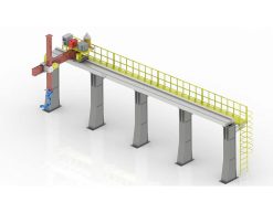
 Robot Linear track
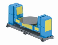 Robot welding Positioner
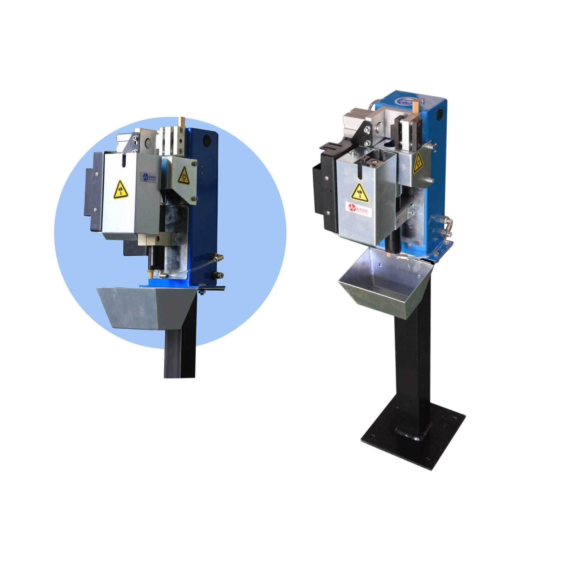 Robot Torch cleaning station
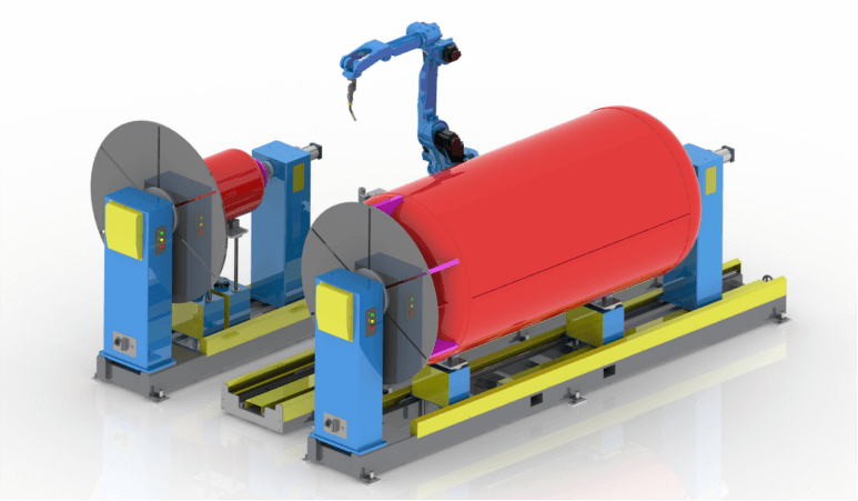 Welding Robot Workstations & Automation Solutions
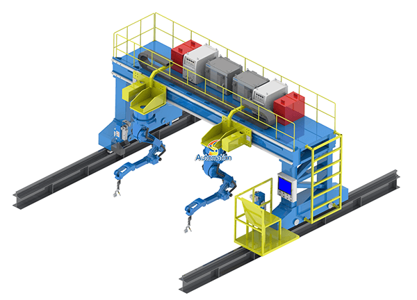 Robot Gantry System
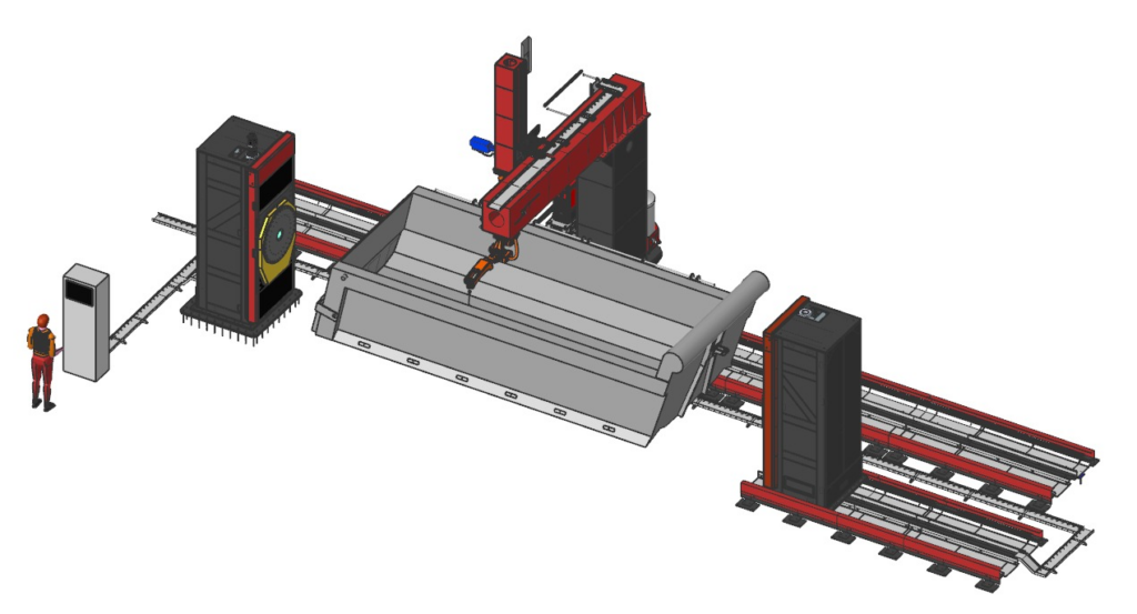
The spool that came back
A pipe spool came back from a customer once. Not the whole job — one spool, out of a batch of forty. The circumferential weld at the flange had a root that was perfect for three quarters of the joint and then opened up, just enough to fail the inspection. The shop had done everything right on paper: the fit-up was checked, the root gap was set with a gauge, the robot program was the same one that had welded the other thirty-nine. The difference was the spool itself. The flange face had gone slightly oval during handling, and the pipe had a few millimetres of out-of-roundness that nobody had measured because the pipe looked round.
That is the thing about pipe work. The positioner is not the hard part. The pipe is. A welding positioner for pipe has to hold a round thing round, rotate it at a steady speed under a torch that never moves, and keep the seam in the same place for the full 360 degrees — while the pipe tries to do everything except stay round. Get the positioner wrong and the symptoms look like welding problems: inconsistent penetration, a root that wanders, a flange that finishes oval. They are not welding problems. They are holding problems, and they start with the choice between a headstock-tailstock and a turntable.
This article is about that choice, and about what pipe diameter, pipe length, and fit-up do to it. It is written for the engineer who has to sign off on a pipe welding cell — or for the shop that is still welding spools by hand and wondering whether a positioner will actually help.
What pipe welding asks of a positioner
A circumferential pipe weld is a strange job for a robot. The torch barely moves. The pipe does the work, rotating under the torch at a speed matched to the travel speed of the weld. The seam has to stay in the flat or near-flat position for the whole rotation, the root gap has to stay constant, and the rotation speed has to stay steady — a weld that starts at the right speed and ends at the wrong one will show it in the bead.
That sets three requirements that matter more than the brand on the nameplate.
First, the pipe has to rotate around its own centreline, not around some nearby point. If the centreline is off by a few millimetres, the seam rises and falls as the pipe turns, the stick-out changes, and the arc length wanders. On a small-bore pipe the effect is worse, because the same absolute error is a bigger share of the diameter.
Second, the rotation has to be smooth and repeatable. A turntable that hesitates at the same point every revolution will put a defect at the same point every revolution. A headstock that slips under load will put a thick bead where it slowed and a thin one where it caught up.
Third, the pipe has to stay round while it is being welded. Heat distorts it. Clamping distorts it. A flange bolted to a faceplate with uneven torque distorts it. The positioner is the thing that either prevents that or causes it, depending on how the pipe is held.
Everything in this article comes back to those three requirements. A headstock-tailstock and a turntable meet them in different ways, and the pipe itself decides which way is right.
The headstock-tailstock: built for long pipe
A headstock-tailstock positioner holds the pipe between two ends: a powered headstock that drives the rotation, and a tailstock that supports the far end. The pipe hangs between them on its own centreline, and the whole length is accessible to the robot.
This is the right answer for long spools. A spool that is two or three metres long cannot be held from one end — it sags, and the sag changes as it rotates, because the heavy end is not always at the bottom. Held between two centres, the same spool stays on its centreline for the full rotation, and the robot can weld the circumferential seams at both ends, the branch connections in the middle, and the longitudinal seam if there is one, without re-clamping.
It is also the right answer for heavy flanges. A large flange is a disc of steel bolted to the end of a pipe, and it is heavy enough to matter. On a headstock-tailstock, the weight is carried at both ends, and the flange can be faced, fitted and welded in the same setup. We have seen shops weld a flange, unbolt it, flip the spool, and re-clock it to find the flange face has moved — that is a clamping problem, not a welding problem, and two-end support is the simplest way to avoid it.
The trade-off is changeover. A headstock-tailstock takes time to set up: the tailstock has to be moved to the right position, the pipe has to be centred, the chuck jaws have to be changed for a different diameter. For a batch of forty identical spools, that is one setup and forty welds, and nobody cares. For a shop that welds three spools of one size and then two of another, the changeover time starts to eat the day. If your work is mostly short runs of different diameters, say so early — it changes the answer.
There is also the question of what holds the pipe. A three-jaw chuck is the usual answer, and it is fine for pipe that is actually round. For pipe that is not quite round — and a surprising amount of it is not — a three-jaw chuck will pull it round at the chuck and leave it oval a metre down the pipe. That is where rollers or a steady rest earn their keep: they support the pipe without forcing it into a shape it does not have. We covered the mechanism of headstock-tailstock positioners in an earlier article; this one is about what happens when real pipe meets them.
The turntable: built for flanges and short spools
A welding turntable — a single-axis rotary table, sometimes with a tilt — holds the workpiece from one end and spins it. The pipe or flange sits on the table, clamped to a faceplate or a chuck, and the robot welds the seam as the table turns.
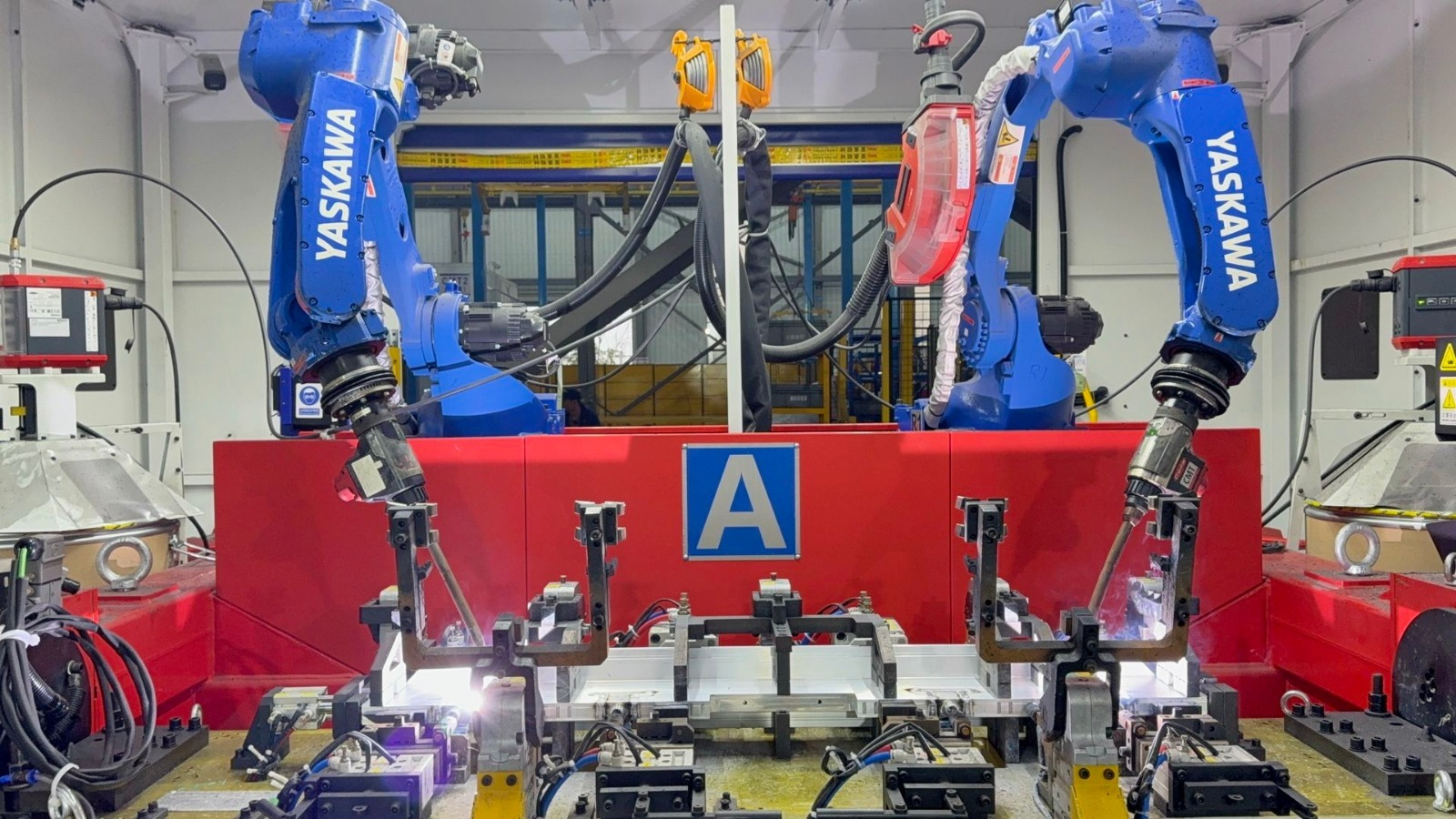
This is the right answer for flanges and short spools. A flange on a turntable is easy to load, easy to clamp, and easy to weld: the joint is right in front of the robot, the rotation is short and stiff, and the whole setup is compact. A short spool with a flange on each end can be welded on a turntable with a simple fixture, one end at a time, and the changeover between sizes is usually a matter of swapping a faceplate or a set of jaws.
It is also the right answer when floor space is tight. A turntable cell is a small cell. A headstock-tailstock cell is a long cell, because the pipe is long and the robot has to reach both ends. If the shop floor is the constraint, that matters as much as the welding does.
The trade-off is the cantilever. A turntable holds the pipe from one end, and everything beyond the chuck is hanging in the air. On a short, stiff spool that is fine. On a long spool it is not: the free end sags, the sag rotates with the pipe, and the seam moves up and down as the table turns. The symptom is a root gap that is right at the chuck and wrong at the far end, and a bead that is perfect on one side of the pipe and thin on the other. The fix is a steady rest or a second support, and at that point you are building a headstock-tailstock out of a turntable, which is a sign you picked the wrong machine.
The other trade-off is load. A turntable has a rated capacity, and the load is not just the weight of the pipe — it is the weight times the distance from the table face. A flange that is well within the weight limit can still be too much if it sits a metre out from the table on a long spool. Check the moment, not just the mass. Our article on how to choose the right welding positioner for heavy-duty robotic welding goes into the load calculation in more detail.
How diameter and length decide
The choice is mostly a function of two numbers: the pipe diameter and the pipe length. Not the catalogue numbers — the actual numbers of the work you do most.
Small diameter, short length — say, pipe under 200 mm diameter and under a metre long — is turntable work. The pipe is stiff enough to hold from one end, the changeover is fast, and the cell is compact. A headstock-tailstock will do the job, but you will spend more time setting it up than welding.
Medium diameter and medium length is where the decision gets interesting. A spool of 300 mm diameter and two metres long can go either way, and the tie-breakers are batch size and flange weight. Long runs of the same size favour the headstock-tailstock, because one setup covers the batch. Mixed work with frequent diameter changes favours the turntable, because the changeover is faster. Heavy flanges favour two-end support. If you are in this band, write down your three most common spool sizes and your typical batch size before you decide — the answer usually falls out of that list.
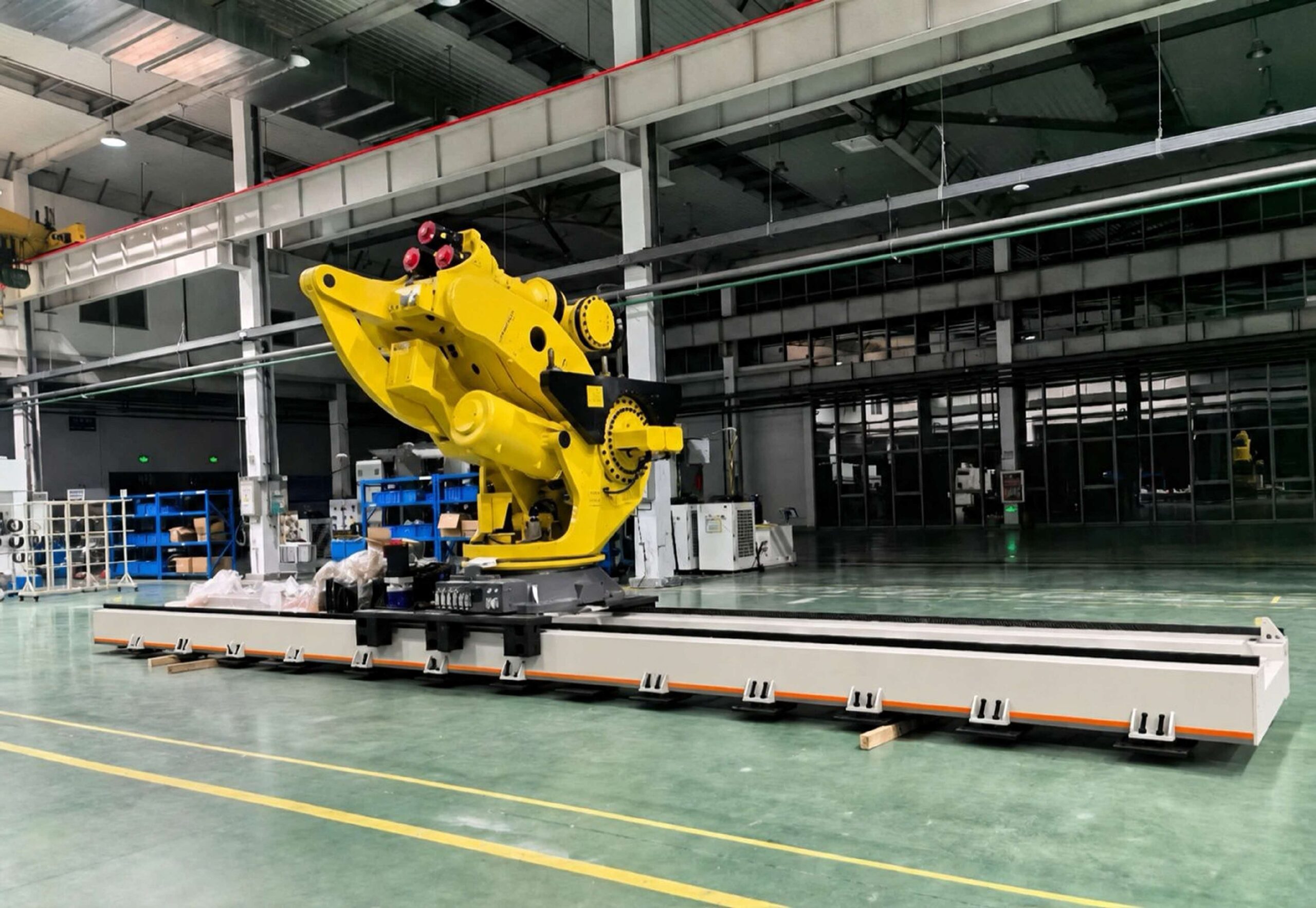
Large diameter, long length — pipe over 500 mm diameter, spools over three metres — is headstock-tailstock work, and often headstock-tailstock plus a track. The pipe is too heavy and too long to cantilever, and the robot cannot reach both ends of a three-metre spool from a fixed position. A 7th-axis track under the robot is the usual answer for the reach problem, and it is worth deciding at the same time as the positioner rather than bolting it on later: a long spool eats robot reach faster than most people expect — see our article on robot track travel versus effective travel.
The fit-up problems nobody budgets for
Fit-up is where pipe welding cells lose their money, and it is almost never in the quotation. Three problems come up again and again.
Ovality. Pipe is not round. It is round-ish. Standard pipe tolerances allow a certain amount of out-of-roundness, and a flange that has been stored flat on a pallet for six months is not the shape it was when it left the factory. The positioner cannot fix ovality, but it can hide it until the worst moment: a chuck that pulls the pipe round at one end leaves the ovality to show up at the weld, where the root gap opens and closes as the pipe rotates. Measure the pipe before you fixture it. A tape measure around the circumference at three points along the spool takes two minutes and saves a day of rework.
Root gap variation. A circumferential weld needs a consistent root gap, and the gap is set by the fit-up, not by the robot. If the pipe end is not square — and a flame-cut pipe end often is not — the gap varies around the circumference, and the robot will weld the same gap differently at different points. The fix is preparation, not programming: face the pipe ends, or at least check them with a square, before the spool goes on the positioner. A fitter with a square is cheaper than a robot re-welding a root.
Heat distortion. Welding a flange onto a pipe puts a ring of heat into the end of the pipe, and the pipe moves. On thin-wall pipe the movement is enough to matter, and it happens while the weld is being made, which means the seam moves under the torch. The usual answers are to weld in a balanced sequence — short runs on opposite sides, rather than one continuous pass — and to let the positioner present the seam in the flat position so the weld pool is stable. A positioner that can rotate the pipe to the right orientation for each pass is doing real work here; a fixed fixture is not. We go into the distortion side of this in our article on reducing welding distortion with a robotic welding positioner.
There is also the humble problem of spatter. Spatter on chuck jaws and on a faceplate changes the clamping from one spool to the next, and a jaw that does not close the same way twice is a positioner that does not repeat. Clean the jaws. It is not a technical point, and it is the one that causes the most unexplained variation we see.
Rotation speed, and why it is not a detail
A circumferential weld lives or dies on rotation speed. The torch is stationary, so the travel speed of the weld is the rotation speed of the pipe surface, and that speed has to match the welding parameters. Too fast and the bead is thin and ropey; too slow and it is wide, with too much heat into the pipe.
The subtlety is that the surface speed depends on the diameter. The same revolutions per minute give a different surface speed on a 150 mm pipe and a 600 mm pipe, and a program written for one diameter will not weld the other. This is the most common programming mistake on pipe cells: the rotation speed is set once, in RPM, and never changed when the diameter changes. The positioner controller needs the diameter, and the program needs to calculate the surface speed from it — or, better, the operator needs a table that says this diameter, this RPM and uses it.
The other subtlety is the tie-in: where the weld starts and ends. A circumferential weld has to overlap its own start by a short distance, and the overlap has to be clean. If the rotation stops exactly where it started, the crater at the end of the weld sits on top of the crater at the beginning, and the result is a lump. The usual answer is to run past the start point by a few degrees and then stop, or to program a crater-fill at the end. Either way, check the stop position on the first article of a batch, not the fortieth.
When the answer is both
Some shops end up with both machines, and that is not a failure of decision-making. A headstock-tailstock for the long spools and a turntable for the flanges and short work is a sensible division, and it keeps the changeover time down on both. The mistake is buying one machine to do both jobs and then fighting it every day.
The other combination worth naming is the positioner plus a track. A long spool needs the robot to reach both ends, and a track is the usual answer — but it has to be specified with the positioner, not after it. Foundation, payload and calibration all interact, and adding a track later costs more than specifying it now.
If you are still welding spools by hand, the honest question is not which positioner but whether the work justifies one at all. A shop welding five spools a week will not pay back a headstock-tailstock quickly. A shop welding fifty will, and the payback is in the rework that stops happening — the spool that does not come back. Count the rework first. It is usually bigger than anyone thinks.
Checklist: specifying a pipe welding positioner
- List your three most common spool sizes (diameter, wall thickness, length) and your typical batch size before choosing a machine.
- Measure ovality on a sample of incoming pipe — tape the circumference at three points along the spool.
- Check the pipe ends are square; face them if they are not, before the spool goes on the positioner.
- Decide headstock-tailstock or turntable on length first, diameter second, batch size third.
- For a turntable, check the overturning moment (weight times distance from the table face), not just the mass.
- For a headstock-tailstock, plan the changeover: tailstock travel, chuck jaw changes, and how long a diameter change takes.
- Specify the rotation speed in surface speed (mm/min at the weld), not just RPM, and keep a diameter-to-RPM table at the cell.
- Plan the tie-in: overlap the weld start by a few degrees and program a crater-fill at the end.
- Put a steady rest or support roller on the list for any spool that sags when held from one end.
- Clean the chuck jaws and faceplate as part of the changeover routine, and check the clamping repeats the same way twice.
FAQ
Can one positioner handle both small-bore and large-diameter pipe?
Up to a point. A headstock-tailstock with a wide chuck range and an adjustable tailstock can cover a broad range of diameters, but the changeover time grows, and a chuck that spans 100 mm to 600 mm will not grip the small pipe as well as a dedicated small chuck. A turntable is more flexible on diameter but limited on length. If your work spans a wide range, two machines — or one machine plus the right set of chucks and faceplates — is usually the honest answer.
Why does a flange go oval after circumferential welding?
Heat. Welding a flange puts a ring of heat into the end of the pipe, and the pipe moves as it cools. The flange itself is stiff, so the movement shows up as a slight ovality in the flange face or the bolt circle. The usual answers are a balanced welding sequence, a fit-up that leaves room for the movement, and facing the flange after welding if the tolerance demands it. The positioner cannot prevent it, but a setup that holds the flange square and lets the pipe expand evenly will keep it small.
Headstock-tailstock or turntable for short spools with flanges on both ends?
A turntable, usually. A short spool with a flange on each end can be welded one end at a time on a turntable with a simple fixture, and the changeover is fast. A headstock-tailstock will do it, but you will spend more time setting up the tailstock than welding. The exception is a heavy spool, where the weight favours two-end support even at short lengths.
How do you keep the root gap consistent while the pipe rotates?
The gap is set by the fit-up, not by the rotation. Face the pipe ends so they are square, check the ovality before fixturing, and clamp the pipe so it stays round at the weld — rollers or a steady rest, not just a chuck. Then verify the gap at four points around the circumference before the first weld. If the gap varies around the joint, fix the fit-up; no amount of program adjustment will save a joint that was wrong before the arc started.
Do I need a track with my pipe welding positioner?
Only if the robot cannot reach the work from a fixed position. A turntable cell rarely needs one. A headstock-tailstock cell with spools over two or three metres usually does, because the robot has to reach both ends of the spool and the branch connections in the middle. Decide the track at the same time as the positioner: the foundation, the payload, and the calibration all interact, and adding a track later costs more than specifying it now.
The spool test
If you are choosing a positioner for pipe work, do not start with the catalogue. Start with three spools from your own floor: the smallest you weld, the longest you weld, and the one with the heaviest flange. Put them on the table — or rather, ask how each machine would hold them, how long the changeover takes, and where the seam sits while the pipe rotates. The machine that holds your worst spool well is the machine that will hold the rest of them.
And if you have a spool that came back, bring it. A failed spool tells you more about what the cell needs than a specification sheet does. Send us your pipe diameter range, wall thickness, spool length, flange sizes, and robot model, and we will tell you which arrangement fits — headstock-tailstock, turntable, or both — and what the fixture needs to look like. You can reach our engineering team through the contact page, or browse our welding positioner range, our robot linear track range, and our gantry system range to see the equipment we build.
By WRS Robotics Engineering Team