 Robot Linear track
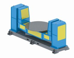 Robot welding Positioner
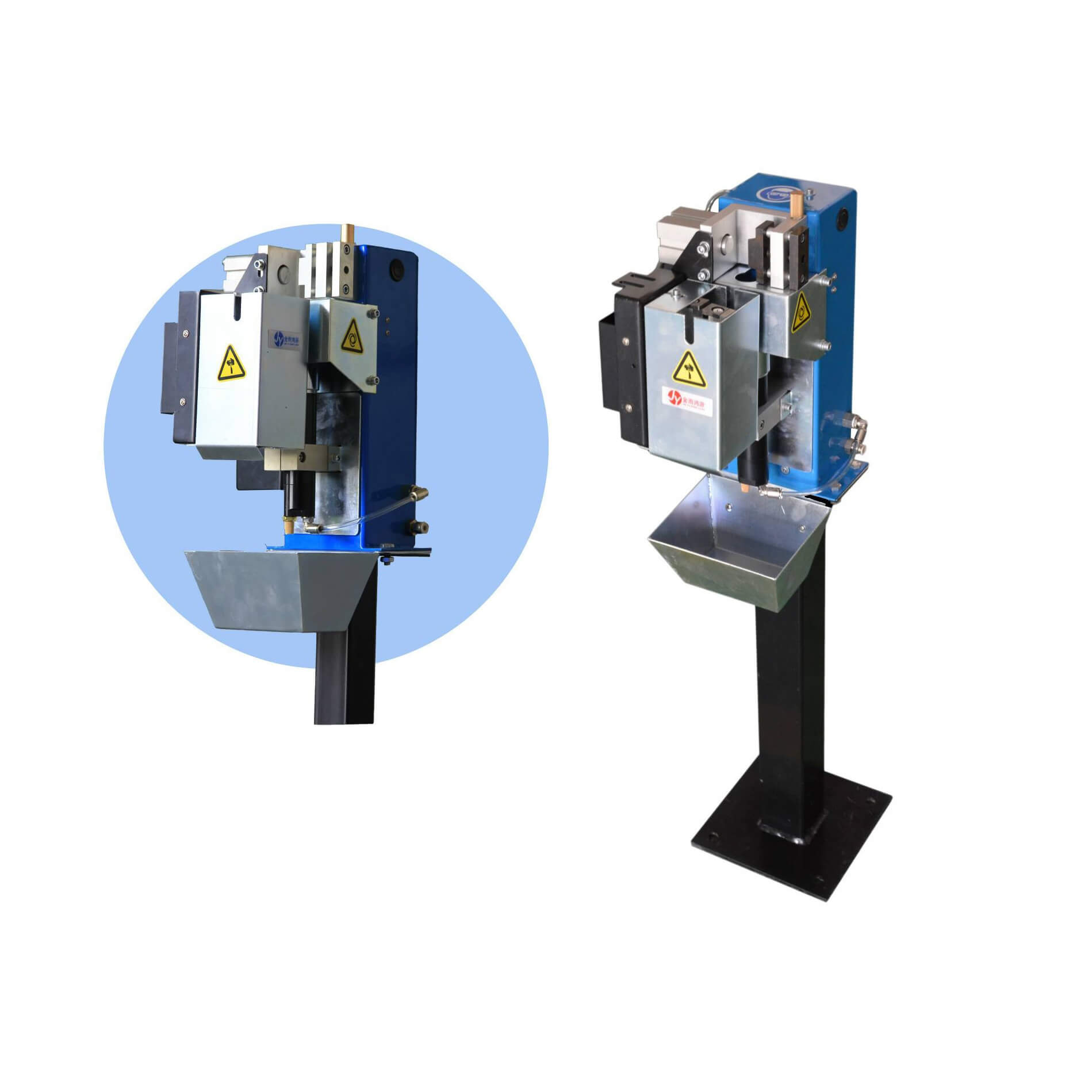 Robot Torch cleaning station
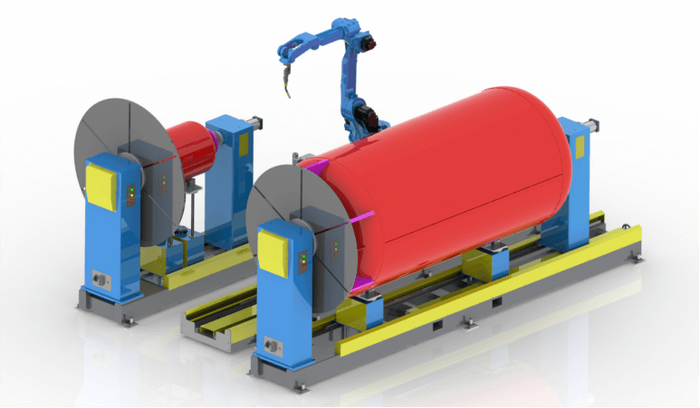 Welding Robot Workstations & Automation Solutions
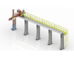
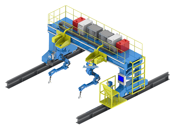 Robot Gantry System
1) Robot / vehicle information
-
Robot model(s), drawings (2D/3D / CAD) and footprint (length × width × height).
-
Robot mass (kg) empty and max payload (kg).
-
Wheel / chassis type (wheels, tracks, omni, Mecanum) and wheelbase.
-
Required travel speed (m/s) and max acceleration (m/s²).
-
Turning radius / minimum turning circle.
-
Mounting points or kinematic constraints (clearance under/around robot).
2) Track functional requirements
-
Purpose: continuous loop, point-to-point, shuttle/return, indexing/accumulation.
-
Throughput (robots per hour) and max simultaneous robots on track.
-
Precision requirements: lateral/longitudinal repeatability (mm).
-
Max travel distance / track length (m).
-
Required stops / stations and dwell time at each station.
-
Direction (uni/bidirectional) and lane count (single/multiple).
3) Environment & site conditions
-
Indoor/outdoor. Temperature range and humidity.
-
Corrosive exposure (chemicals, salt, spray).
-
Cleanroom / dust class or IP requirements.
-
Floor type, existing structures, obstructions, floor flatness/tolerance.
-
Seismic/earthquake loading or vibration sources (if any).
4) Track geometry & civil constraints
-
Available floor plan / route (DXF/CAD preferred).
-
Max allowable width & height envelope.
-
Required clearances left/right/top (mm).
-
Elevation changes (ramps, gradients) and max slope %.
-
Minimum bend radius for curves.
-
Expansion joints / floor penetrations allowed?
5) Mechanical & structural requirements
-
Max static and dynamic loads on track (N) — include worst-case robot + payload.
-
Allowable deflection (mm) under load.
-
Speed at curves (max) and required transition radii.
-
Material preferences (steel, stainless, aluminum, polymer) & corrosion class.
-
Fatigue life / duty cycle (cycles per day, expected years of service).
6) Drive & guidance
-
Track drive type: driven rail, chain, belt, motorized rollers, linear motor, passive guide.
-
If driven: drive motor locations, gearbox preferences, backlash limits.
-
Guidance method: physical guide rails, magnetic strip, optical line, fiducials, track slots.
-
Tolerance for lateral play and vertical runout.
7) Power, controls & communication
-
Power supply available at site (voltage, phases, grounding).
-
On-track power delivery method (busbars, contact rails, inductive power, battery swap).
-
Control architecture: PLC, fieldbus (EtherCAT, Profinet, Modbus), CAN, Wi-Fi.
-
Positioning & feedback: encoders, RFID, absolute linear encoder, laser/vision.
-
Safety integration: E-stop, safety PLC, light curtains, safety-rated speed monitoring.
8) Safety & standards
-
Applicable standards / certifications (CE, UL, ISO 13849, ISO 10218, local regulations).
-
Required safety distances, guarding, and access panels.
-
Emergency stop locations and behavior (hot stop vs controlled stop).
-
Lockout / tagout requirements for maintenance.
9) Installation, maintenance & spare parts
-
Site access constraints (doors, lifts, crane availability).
-
Installation tolerances and required anchoring method (chemical anchor, weld, bolt).
-
Routine maintenance tasks and frequency (lubrication, tensioning, sensor cleaning).
-
Spare parts list and expected lead times.
10) Performance, testing & acceptance
-
Factory acceptance tests (FAT) and onsite acceptance tests (SAT) criteria.
-
Acceptance metrics (speed, repeatability, uptime %, noise level).
-
Warranty period and post-warranty support expectations.
11) Project constraints
-
Budget range (or maximum).
-
Target delivery / installation date.
-
Single supplier vs split-sourcing (mechanical vs controls).
-
Preferred vendors / components (motors, drives, PLCs).
12) Documentation & deliverables you want
-
CAD (STEP/IGES), 2D layout (DWG), BOM, wiring diagrams, PLC program, HMI screens, operation manual, maintenance manual, test reports.
Example spec sheet (copy & edit)
Use this to quickly give your design team the minimum info.
-
Project name: __________________
-
Track type: continuous loop / shuttle / single lane (circle one)
-
Track length (total): 120 m
-
Robot model: RBT-X100 — footprint 600×400×900 mm (L×W×H)
-
Robot mass: 90 kg empty, 180 kg max payload
-
Max speed: 1.2 m/s; cruise 0.8 m/s; max accel 0.5 m/s²
-
Min turning radius: 0.6 m
-
Throughput: 20 robots/hour; max concurrent robots: 4
-
Guidance: physical guide rail + absolute encoder every 5 m
-
Drive: motorized chain with 1:30 gearbox, located at ~every 15 m
-
Power: 400 V AC 3-phase onsite; on-track power via busbar + onboard conversion
-
Control: EtherCAT slave nodes, central PLC, local motor controllers
-
Environment: indoor, 5–40°C, non-corrosive
-
Safety: ISO 13849 PL d; E-stop at every 10 m; guarded access panels
-
Materials: painted Q235 steel with stainless fasteners in wet zones
-
Expected duty: 16 h/day, 6 days/week; design life 10 years
-
FAT/SAT: functional check of speed/stop accuracy; repeatability ≤ ±5 mm
-
Budget: $______; Delivery: Q4 2025
-
Deliverables: 3D layout, BOM, wiring diagrams, PLC code, maintenance manual
Helpful engineering notes & quick formulas
-
Required traction force: F = m·a + rolling_resistance.
-
rolling_resistance ≈ m·g·Crr (Crr ~0.02 for wheels on steel/roller; adjust for your type).
-
-
Motor torque: T = F × r (r = wheel radius). Add safety factor 1.5–2 for startup.
-
Stopping distance: d = v² / (2·a). Use this to size braking zones and station spacing.
-
Bend radius & speed: reduce speed at curves to limit lateral acceleration: a_lat = v² / R. Keep a_lat comfortable (e.g., <0.5–1.0 m/s² for sensitive payloads).
What I can produce for you next (no need to decide now)
-
A ready-to-send spec template (customized to your robot) for vendors/engineers.
-
Preliminary layout (2D plan) if you upload a floor plan.
-
Rough BOM + estimated cost range based on your budget.
-
Motor/drive torque calculations if you provide wheel radius and target accel.
If you want, paste your robot’s key numbers (footprint, mass, wheel radius, desired max speed) and I’ll compute the traction/motor torque and stopping distance right away and give a recommended drive arrangement.